
HP VPN Firewall Appliances High Availability Configuration Guide

40
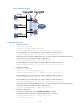
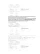
The output shows that in VRRP group 1 Firewall A is the master, Firewall B is the backup and the
host with the default gateway of 202.38.160.111/24 accesses the Internet through Firewall A. In
VRRP group 2 Firewall A is the backup, Firewall B is the master and the host with the default
gateway of 202.38.160.112/24 accesses the Internet through Firewall B.
NOTE:
To implement load balancing between the VRRP groups, be sure to confi
g
ure the default
g
ateway as
202.38.160.111 or 202.38.160.112 on the hosts on network segment 202.38.160.0/24.
IPv6 VRRP configuration examples
Single VRRP group configuration example
Network requirements
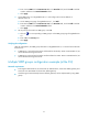
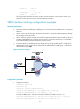
• Firewall A and Firewall B belong to VRRP group 1 with the virtual IPv6 addresses of 1::10/64 and
FE80::10.
• Host A wants to access Host B on the Internet. Host A learns 1::10/64 as its default gateway through
the RA messages sent by the routers.
• When Firewall A operates correctly, packets sent from Host A to Host B are forwarded by Firewall
A. When Firewall A fails, packets sent from Host A to Host B are forwarded by Firewall B.
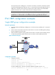
Figure 24 Network diagram
Configuration procedure
1. Configure Firewall A:
<FirewallA> system-view
[FirewallA] ipv6
[FirewallA] interface gigabitethernet0/1
[FirewallA-GigabitEthernet0/1] ipv6 address fe80::1 link-local
[FirewallA-GigabitEthernet0/1] ipv6 address 1::1 64
# Create a VRRP group 1 and set its virtual IPv6 addresses to FE80::10 and 1::10.
[FirewallA-GigabitEthernet0/1] vrrp ipv6 vrid 1 virtual-ip fe80::10 link-local