
HP VPN Firewall Appliances High Availability Configuration Guide

82
Hardware Com
p
atibilit
y
20-Gbps VPN firewall modules No
Network requirements
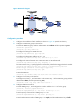
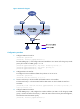
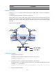
As shown in Figure 40, Firewall A and Firewall B belong to VRRP group 1, whose virtual IP address is
192.168.0.10.
The default gateway of the hosts in the LAN is 192.168.0.10.
When Firewall A works correctly, hosts in the LAN access the external network through Firewall A. When
Firewall A detects that the uplink is down through BFD, it decreases its priority so that Firewall B can
preempt as the master, ensuring that the hosts in the LAN can access the external network through
Firewall B.
Figure 40 Network diagram
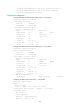
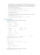
Configuration procedure
1. Configure BFD on Firewall A:
# Configure the source address of BFD echo packets as 10.10.10.10.
<FirewallA> system-view
[FirewallA] bfd echo-source-ip 10.10.10.10
2. Create the track entry to associate with the BFD session on Firewall A:
# Create track entry 1 for the BFD session on Firewall A to check whether the uplink device with the
IP address 1.1.1.2 is reachable.
[FirewallA] track 1 bfd echo interface gigabitethernet1/1 remote ip 1.1.1.2 local ip
1.1.1.1
3. Configure VRRP on Firewall A: