
HP VPN Firewall Appliances High Availability Configuration Guide

90
VRRP-Track-interface management collaboration configuration
example
In this example, the master monitors the uplink interface.
Network requirements
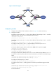
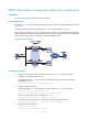
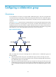
As shown in Figure 42, Host A needs to access Host B on the Internet. The default gateway of Host A is
10 .1.1.10 / 2 4 .
Firewall A and Firewall B belong to VRRP group 1, whose virtual IP address is 10.1.1.10.
When Firewall A operates correctly, packets from Host A to Host B are forwarded through Firewall A.
When VRRP detects that a fault is on the uplink interface of Firewall A through the interface management
module, packets from Host A to Host B are forwarded through Firewall B.
Figure 42 Network diagram
Configuration procedure
1. Configure the IP address of each interface as shown in Figure 42. (Details not shown.)
2. Configure a track entry on Firewall A:
# Configure track entry 1, and associate it with the physical status of the uplink interface
GigabitEthernet 0/2.
[FirewallA] track 1 interface gigabitethernet0/2
3. Configure VRRP on Firewall A:
# Create VRRP group 1, and configure the virtual IP address 10.1.1.10 for the group.
[FirewallA] interface gigabitethernet0/1
[FirewallA-GigabitEthernet0/1] vrrp vrid 1 virtual-ip 10.1.1.10
# Set the priority of Firewall A in VRRP group 1 to 110.
[FirewallA-GigabitEthernet0/1] vrrp vrid 1 priority 110
# Configure to monitor track entry 1 and specify the priority decrement as 30.
[FirewallA-GigabitEthernet0/1] vrrp vrid 1 track 1 reduced 30
4. Configure VRRP on Firewall B:
<FirewallB> system-view
[FirewallB] interface gigabitethernet0/1