HP VPN Firewall Appliances NAT and ALG Configuration Guide Part number: 5998-4166 Software version: F1000-A-EI/F1000-S-EI (Feature 3726) F1000-E (Release 3177) F5000 (Feature 3211) F5000-S/F5000-C (Release 3808) VPN firewall modules (Release 3177) 20-Gbps VPN firewall modules (Release 3817) Document version: 6PW101-20130923
Legal and notice information © Copyright 2013 Hewlett-Packard Development Company, L.P. No part of this documentation may be reproduced or transmitted in any form or by any means without prior written consent of Hewlett-Packard Development Company, L.P. The information contained herein is subject to change without notice.
Contents Configuring NAT ·························································································································································· 1 Overview············································································································································································ 1 NAT control ·······································································································································
Configuring a NAT-PT prefix ········································································································································ 38 Configuring IPv4/IPv6 address mappings on the IPv6 side ······················································································ 38 Configuring a static mapping on the IPv6 side ·································································································· 38 Configuring a dynamic mapping policy on the IPv6 s
Support and other resources ····································································································································· 71 Contacting HP ································································································································································ 71 Subscription service ·············································································································································· 71 Re
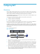
Configuring NAT Overview Network Address Translation (NAT) provides a way to translate an IP address in the IP packet header to another IP address. NAT enables a large number of private users to access the Internet by using a small number of public IP addresses. NAT effectively alleviates the depletion of IP addresses. A private IP address is used only in an internal network, whereas a public or external IP address is used on the Internet and is globally unique.
The NAT operation is transparent to the terminals involved. The external server believes that the IP address of the internal PC is 20.1.1.1 and is unaware of the private address 192.168.1.3. As such, NAT hides the private network from the external networks. Despite the advantages of allowing internal hosts to access external resources and providing privacy, NAT also has the following disadvantages: • Because NAT involves translation of IP addresses, the IP headers cannot be encrypted.
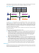
NAPT mapping is based on both the IP address and the port number. With NAPT, packets from multiple internal hosts are mapped to the same external IP address with different port numbers. Figure 2 NAPT operation Host A 192.168.1.2 Direction Before NAT After NAT Outbound 192.168.1.2:1111 20.1.1.1:1001 Outbound 192.168.1.2:2222 20.1.1.1:1002 Outbound 192.168.1.3:1111 20.1.1.1:1003 Packet 1 Src : 192.168.1.2:1111 Packet 1 Src : 20.1.1.1:1001 Packet 2 Src : 192.168.1.2:2222 192.168.1.
You can configure an internal server on the NAT device by mapping a public IP address and port number to the private IP address and port number of the internal server. For instance, you can configure an address like 20.1.1.12:8080 as an internal Web server's external address and port number.
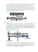
Easy IP Easy IP uses the public IP address of an interface on the device as the translated source address to save IP address resources, and uses ACLs to permit only certain internal IP addresses to be NATed. NAT support for VPNs NAT allows users from different VPNs to access external networks through the same outbound interface, and allows the VPN users to use the same private address space. 1.
Configuration guidelines Follow these guidelines when you configure NAT: • An address pool can contain a maximum of 255 addresses. • On certain types of devices, an address pool cannot include addresses in other address pools, IP addresses of interfaces with Easy IP enabled, or public addresses of internal servers. • Low-priority address pools cannot include addresses in non low-priority address pools, external IP addresses for one-to-one NAT, and public addresses of internal servers.
Creating an address pool 1. From the navigation tree, select Firewall > NAT Policy > Dynamic NAT. The dynamic NAT configuration page appears. Figure 5 Dynamic NAT configuration page TIP: You can click the ID link of an ACL to view details about the ACL, and create and delete ACL rules. For more information about ACL configuration, see Access Control Configuration Guide. 2. In the Address Pool area, click Add. The Add NAT Address Pool page appears. Figure 6 Adding NAT Address Pool page 3.
Item End IP Address Description Specify the end IP address of the address pool. The end IP address must be identical to or higher than the start IP address. Configure the address pool as a low-priority or a non low-priority address pool. IMPORTANT: Low priority This configuration item is applicable for asymmetric-path stateful failover only. The low priority settings for the local and peer devices must be different. Configuring dynamic NAT on an interface 1.
Item Description Select an address translation mode: • PAT—Refers to NAPT. In this mode, associating an ACL with an address pool translates both IP addresses and port numbers. Address Transfer • No-PAT—Refers to many-to-many NAT. In this mode, associating an ACL with an address pool translates only IP addresses. • Easy IP—In this mode, the NAT gateway directly uses an interface's public IP address as the translated IP address, and uses an ACL to match IP packets.
Figure 8 Static NAT configuration page 2. In the Static Address Mapping area where static address mappings are displayed, click Add to enter the Add Static Address Mapping page. Figure 9 Adding Static Address Mapping page 3. Configure a static address mapping as described in Table 3. 4. Click Apply. Table 3 Configuration items Item Description Specify a name of the VPN instance to which the internal IP addresses belong.
Item Description Specify a name of the VPN instance to which the external IP addresses belong. Global VPN Instance If no global VPN instance is specified, this indicates that the external address is a common public network address. Global IP Address Enter a public IP address for the static address mapping. Specify the network mask for internal and public IP addresses. Network Mask If the network mask is specified, net-to-net static NAT is implemented.
Configure basic internal server settings 1. From the navigation tree, select Firewall > NAT Policy > Internal Server. The internal server configuration page appears. Figure 11 Internal server configuration page 2. In the Internal Server area, click Add. The Add Internal Server page appears.
Figure 12 Adding Internal Server page 3. Configure the internal server as described in Table 5. 4. Click Apply. Configure advanced internal server settings 1. Click Advanced in the page shown in Figure 13. The Advanced Configuration page appears.
Figure 13 Configuring advanced internal server settings 2. Configure the internal server as described in Table 5. 3. Click Apply. Table 5 Configuration items Item Description Interface Specify an interface to which the internal server policy is applied. Select the protocol to be carried by IP (Only supported by advanced configuration).
Item Description Specify the global port numbers for the internal server. This option is available when 6(TCP) or 17(UDP) is selected as the protocol type. You can: • For common configuration—Use the single box to specify a global port. 0 Global Port represents the default port of the specified service type. If the selected service type is any(TCP) or any(UDP), the global port is any port.
Item Description Enable track to VRRP Configure whether to associate the internal server on an interface with a VRRP group, and specify the VRRP group to be associated if you associate the internal server on an interface with a VRRP group. When two network devices deliver both stateful failover and dynamic NAT, • Make sure each address pool on an interface is associated with one VRRP group VRRP Group only.
Item Description Internal IP Enter the IP addresses of the internal server. Enter the port number of the internal server. Internal Port This option is available when 6(TCP) or 17(UDP) is selected for the protocol type. If you enter 0 in the field, all types of services are provided. Value 0 indicates a static connection exists between the internal address and external address. Configuring DNS mapping 1. From the navigation tree, select Firewall > NAT Policy > Internal Server. 2.
Figure 16 Network diagram Configuring Firewall 1. Configure an ACL to permit internal users in subnet 10.110.10.0/24 to access the Internet: a. From the navigation tree, select Firewall > ACL. b. Click Add. c. Enter 2001 in ACL Number, and click Apply. Figure 17 Defining ACL 2001 d. Click the icon in the operation column corresponding to ACL 2001 to enter the ACL 2001 configuration page. e. Click Add. f. On the page that appears, create an ACL rule: − Select Permit in Operation.
Figure 18 Configuring ACL 2001 to permit users on network 10.110.10.0/24 to access the Internet g. Click Add on the ACL 2001. Select Deny for Operation, and click Apply. Figure 19 Configuring ACL 2001 to prohibit other users to access the Internet 2. Configure a NAT address pool: a. From the navigation tree, select Firewall > NAT Policy > Dynamic NAT. b. Click Add. c. On the page that appears as shown in Figure 20, enter 0 in Index, enter 202.38.1.2 in Start IP Address and enter 202.38.1.
Figure 21 Configuring dynamic NAT Internal server configuration example Network requirements As illustrated in Figure 22, a company provides two Web servers and one FTP server for external users to access. The internal network address is 10.110.0.0/16. The internal address for the FTP server is 10.110.10.3/16, for the Web server 1 is 10.110.10.1/16, and for the Web server 2 is 10.110.10.2/16. The company has three public IP addresses from 202.38.1.1/24 through 202.38.1.3/24.
f. Enter 10.110.10.3 in the Internal IP field. g. Select the service type ftp. h. Click Apply. Figure 23 Configuring an internal FTP server 2. Configure the Web server 1: a. Click Add in the Internal Server area. b. On the page that appears, select GigabitEthernet0/1 for Interface. c. Select the Assign IP Address option, and enter 202.38.1.1. d. Select the first option for Global Port and enter 80. e. Enter 10.110.10.1 in the Internal IP field. f. Select the service type www. g. Click Apply.
Figure 24 Configuring internal Web server 1 3. Configure the Web server 2: a. Click Add in the Internal Server area. b. On the page that appears, select GigabitEthernet0/1 for Interface. Select the Assign IP Address option, and enter 202.38.1.1. Select the first option for Global Port and enter 8080. Enter 10.110.10.2 in the Internal IP field. Select the service type www. c. Click Apply.
Figure 25 Configuring internal Web server 2 Configuring NAT at the CLI NAT configuration task list Task Remarks Configure address translation: • Configuring static NAT • Configuring dynamic NAT Either is required. Configuring an internal server Required. Configuring DNS mapping Optional.
Configuring static NAT Static NAT supports NAT multiple-instance as long as the VPN instance of an IP address is provided. Static NAT supports two modes: one-to-one and net-to-net. Configuring one-to-one static NAT One-to-one static NAT translates a private IP address into a public IP address. To configure one-to-one static NAT: Step Command 1. Enter system view. system-view 2. Configure a one-to-one static NAT mapping.
Configuring NAT address pools You can configure NAT address pools in the following ways: • Configure an address pool that consists of a set of consecutive addresses. • Configure an address group that can contain several members. Each member specifies an address pool that consists of a set of consecutive addresses. The address pools of members might not be consecutive. The NAT device selects an IP address from a specific NAT address pool as the source address of a packet.
Step Command 1. Enter system view. system-view 2. Enter interface view. interface interface-type interface-number 3. Configure No-PAT by associating an ACL with an IP address pool on the outbound interface for translating only IP addresses.
Step Command Remarks 1. Enter system view. system-view N/A 2. Enter interface view. interface interface-type interface-number N/A • nat server [ index | acl-number ] protocol pro-type global 3. Configure a common internal server.
Step Command 1. Enter system view. system-view 2. Enter interface view. interface interface-type interface-number 3. Configure an internal server based on ACL. nat server protocol pro-type global acl-number inside local-address [ local-port ] [ vpn-instance local-name ] Configuring DNS mapping With DNS mapping, an internal host can access an internal server on the same private network by using the domain name of the internal server when the DNS server resides on the public network.
Figure 26 Network diagram Configuration procedure # As shown in Figure 26, configure the IP addresses for the interfaces. (Details not shown.) # Configure a one-to-one static NAT mapping. system-view [Firewall] nat static 10.110.10.8 202.38.1.100 # Enable static NAT on interface GigabitEthernet 0/2.
# Associate address pool 1 and ACL 2001 with the outbound interface GigabitEthernet 0/2.
[Firewall-GigabitEthernet0/2] nat server protocol tcp global 202.38.1.1 8080 inside 10.110.10.2 www # Configure the internal SMTP server. [Firewall-GigabitEthernet0/2] nat server protocol tcp global 202.38.1.1 smtp inside 10.110.10.4 smtp [Firewall-GigabitEthernet0/2] quit NAT DNS mapping configuration example Network requirements As shown in Figure 29, a company provides Web and FTP services to external users, and uses internal IP network segment 10.110.0.0/16.
[Firewall] quit Verifying the configuration # After completing the configurations, display the DNS mapping configuration information. display nat dns-map NAT DNS mapping information: There are currently 2 NAT DNS mapping(s) Domain-name: www.server.com Global-IP : 202.38.1.2 Global-port: 80(www) Protocol : 6(TCP) Domain-name: ftp.server.com Global-IP : 202.38.1.2 Global-port: 21(ftp) Protocol : 6(TCP) Host A and Host B can use the domain name www.server.
3. Use the display acl command to verify that the firewall permits external access to the internal network. For more information about firewall, see Attack Protection Configuration Guide.
Configuring NAT-PT NAT-PT can be configured only at the CLI. NAT-PT is not supported on VLAN interfaces and does not support VPN instances, IPv4 fragments, or ICMPv6 fragments. Overview Because of the coexistence of IPv4 networks and IPv6 networks, Network Address Translation–Protocol Translation (NAT-PT) was introduced to realize translation between IPv4 and IPv6 addresses. For example, it can enable a host in an IPv6 network to access the FTP server in an IPv4 network.
• NAPT-PT Network Address Port Translation–Protocol Translation (NAPT-PT) realizes the TCP/UDP port number translation besides static or dynamic address translation. With NAPT-PT, different IPv6 addresses can correspond to one IPv4 address. Different IPv6 hosts are distinguished by different port numbers so that these IPv6 hosts can share one IPv4 address to accomplish the address translation and save IPv4 addresses.
4. Forwards the packet and stores the mappings. After the source and destination IPv6 addresses of the packet are translated into IPv4 addresses, the NAT-PT device forwards the packet to the IPv4 host. Meanwhile, the IPv4/IPv6 address mappings are stored in the NAT-PT device. 5. Forwards the reply packet according to the stored mappings.
NAT-PT supports ICMP, DNS, FTP, and other protocols that employ the network layer protocol but have no address information in the protocol messages. Protocols and standards • RFC 2765, Stateless IP/ICMP Translation Algorithm • RFC 2766, Network Address Translation - Protocol Translation (NAT-PT) NAT-PT configuration task list Complete the following tasks to configure NAT-PT to allow active access from an IPv4 host to an IPv6 host: Task Remarks Enabling NAT-PT Required.
Enabling NAT-PT After NAT-PT is enabled on both the IPv4 network interface and the IPv6 network interface, the device can implement translation between IPv4 and IPv6 addresses. Follow these guidelines when you enable NAT-PT: • The natpt enable command enables both NAT-PT and Address Family Translation (AFT). For information about AFT, see VPN Configuration Guide. • Do not configure NAT-PT mapping policies and AFT policies on the same device. To enable NAT-PT: Step Command Remarks 1.
If the destination IPv4 address in a packet sent from an IPv4 host to an IPv6 host matches the static mapping, the destination IPv4 address is translated into the corresponding IPv6 address. • To configure a static IPv4/IPv6 address mapping on the IPv6 side: Step Command 1. Enter system view. system-view 2. Configure a static IPv4/IPv6 address mapping on the IPv6 side.
Step Command Remarks Skip this step if you use policy 2 or policy 4. 2. Configure a NAT-PT address pool. natpt address-group group-number start-ipv4-address end-ipv4-address You cannot configure a NAT-PT address pool and an AFT address pool with the same number at the same time. • Associate an IPv6 ACL with an address pool: natpt v6bound dynamic acl6 number acl-number address-group address-group [ no-pat ] • Associate an IPv6 ACL with an interface address: 3.
Step Command 1. Enter system view. system-view 2. Configure a static IPv4/IPv6 address mapping on the IPv4 side. natpt v4bound static ipv4-address ipv6-address Configuring a dynamic mapping policy on the IPv4 side A dynamic IPv4/IPv6 address mapping policy on the IPv4 side is that if the source IPv4 address matches a specific ACL, the source IPv4 address is added with a NAT-PT prefix as the translated IPv6 address.
Step Set the Traffic Class field in IPv6 packets translated from IPv4 packets to 0. 2. Command Remarks natpt turn-off traffic-class By default, the value of the Traffic Class field of IPv6 packets is the same as that of the ToS field in corresponding IPv4 packets. Configuring static NAPT-PT mappings of IPv6 servers Generally, a server such as the FTP server, Web server, or Telnet server on an IPv6 network provides services for IPv6 hosts only.
Task Command Remarks Clear all NAT-PT statistics information. reset natpt statistics Available in user view. The reset natpt statistics command cannot clear the statistics of total sessions and total address mappings. NAT-PT configuration examples Configuring dynamic mapping on the IPv6 side Network requirements As shown in Figure 32, Router B with IPv6 address 2001::2/64 on an IPv6 network wants to access Router A with IPv4 address 8.0.0.
# Associate the prefix with the address pool for IPv6 hosts accessing IPv4 hosts. [Firewall] natpt v6bound dynamic prefix 3001:: address-group 1 2. Configure Router A on the IPv4 side: # Configure an IP address for GigabitEthernet 0/1. system-view [RouterA] interface gigabitethernet 0/1 [RouterA-GigabitEthernet0/1] ip address 8.0.0.2 255.255.255.0 [RouterA-GigabitEthernet0/1] quit # Configure a static route to subnet 9.0.0.0/24. [RouterA] ip route-static 9.0.0.0 24 8.0.0.1 3.
[Firewall] interface gigabitethernet 0/1 [Firewall-GigabitEthernet0/1] ip address 8.0.0.1 255.255.255.0 [Firewall-GigabitEthernet0/1] natpt enable [Firewall-GigabitEthernet0/1] quit [Firewall] interface gigabitethernet 0/2 [Firewall-GigabitEthernet0/2] ipv6 address 2001::1/64 [Firewall-GigabitEthernet0/2] natpt enable [Firewall-GigabitEthernet0/2] quit # Configure a NAT-PT prefix. [Firewall] natpt prefix 3001:: # Configure a static IPv4/IPv6 mapping on the IPv4 side. [Firewall] natpt v4bound static 9.0.0.
2. During debugging, check whether the source address of a packet is translated successfully. If not, it is possible that the address pool has no sufficient IP addresses. 3. You can configure a larger address pool, or use NAPT-PT to perform NAT-PT.
NAT444 The device does not support stateful failover of the NAT444 feature. NAT444 can be configured only at the CLI. Feature and hardware compatibility Hardware NAT444 compatibility F1000-A-EI/F1000-S-EI No F1000-E No F5000 No F5000-S/F5000-C No VPN firewall modules Yes 20-Gbps VPN firewall modules Yes Overview NAT444 translates an IPv4 address to another IPv4 address to a third IPv4 address.
Figure 34 Assigning port blocks Static mappings Figure 35 User tracing process Transition technology deployment scheme contains two IP-port mapping modes: static and dynamic. • Static IP-port mapping mode—AAA and Carrier Grade NAT (CGN) set parameters through the network management system and execute the same algorithm for generating mappings. During address tracing process, AAA and CGN do not exchange mappings with each other, and trace the address directly.
• When a great number of users are going online and offline, generation of large number of syslogs and RADIUS packets increases the load of AAA servers or log servers. Thus, log servers cannot meet the requirements and AAA servers' performance might be affected. • Syslogs and RADIUS packets are UDP packets and dynamic IP-port mappings might be lost. • In dynamic IP-port mapping mode, storing mappings is supposed to be time-phrased.
When static NAT444, dynamic NAT444, static NAT, and dynamic NAT all exist and are used for matching the same flows, the matching sequence is as follows: 1. Static NAT. 2. Static NAT444. 3. For dynamic NAT444 and dynamic NAT, ACLs are matched in descending order. Configuring NAT444 static IP-port mappings By configuring an internal-to-external IP-port mapping manually, NAT444 assigns a public address and a port block to each user of the private address pool.
connection. For the following connections of the user, the public port is obtained from the assigned port block for the source address's translation. When all connections from the user are closed, the assigned IP-port block is released. Associate an ACL with an address pool on an interface to enable dynamic NAT444. Configure dynamic NAT444 on the outbound interface of a NAT device, and if needed, configure it on multiple outbound interfaces for an internal host.
Address and Port-Dependent Mapping—For packets with the same source address and source port number but different destination addresses and destination port numbers, different NAT444 mappings apply so that the source address and port number are mapped to the same external IP address but different port numbers. The NAT444 gateway allows the hosts only on the corresponding external networks where these destination addresses reside to access the internal network.
Task Command Remarks Display NAT444 dynamic IP-port mappings. display nat444 dynamic-ip-port-block Available in any view. NAT444 configuration examples Network requirements NAT444 gateways can be designed in a MAN with BRASs or core routers (CRs) through bypass mode to interconnect an IPv4 network with an IPv6 network.
Figure 38 A CR with 1 to n NAT444 gateways network diagram NAT444-1 IPv4 network IPv6 network IPv4 network NAT444-3 IPv6 network CR-1 CR-1 CR-2 NAT444-2 NAT444-1 MAN MAN NAT444-4 NAT444-2 BRAS-2 CR-2 BRAS-1 Bridging users SR-1 SR-2 BRAS-2 Routing users BRAS-1 Bridging users a) Centralized bypass NAT444 SR-1 SR-2 Routing users b) Centralized inserted card NAT444 Configuration procedure This configuration example is only for the NAT444 device.
• 192.168.1.5 <-> 201.1.1.1 : (14001 - 15000 ) 192.168.1.6 <-> 201.1.1.1 : (15001 - 16000 ) 192.168.1.7 <-> 201.1.1.1 : (16001 - 17000 ) 192.168.1.8 <-> 201.1.1.1 : (17001 - 18000 ) 192.168.1.9 <-> 201.1.1.1 : (18001 - 19000 ) 192.168.1.10 <-> 201.1.1.1 : (19001 - 20000 ) 192.168.1.11 <-> 201.1.1.2 : (10001 - 11000 ) 192.168.1.12 <-> 201.1.1.2 : (11001 - 12000 ) 192.168.1.13 <-> 201.1.1.2 : (12001 - 13000 ) 192.168.1.14 <-> 201.1.1.2 : (13001 - 14000 ) 192.168.1.
[Sysname] display nat444 dynamic-ip-port-block Dynamic NAT444 IP-port-block tables: (Used: 3, Unused:97) Local-IP <-> Global-IP 192.168.1.1 <-> 201.1.1.1 : (10001 - 11000) : 252, --- 192.168.1.2 <-> 201.1.1.1 : (11001 - 12000) : 252, --- 192.168.1.3 <-> 201.1.1.
Configuring ALG Application Level Gateway (ALG) processes the payload information of application layer packets to make sure data connections can be established. Usually NAT translates only IP address and port information in packet headers and does not analyze fields in application layer payloads. However, the packet payloads of some protocols might contain IP address or port information, which can cause problems if not translated.
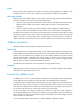
ALG process The following example describes the FTP operation of an ALG-enabled device. As shown in Figure 39, the host on the external network accesses the FTP server on the internal network in passive mode through the ALG-enabled device. Figure 39 Network diagram for ALG-enabled FTP application in passive mode The communication process includes the following steps: 1. Establishing a control connection. The host sends a TCP connection request to the server.
4. Exchanging data. The host and the FTP server exchange data through the established data connection. Configuring ALG in the Web interface By default, ALG is enabled only for FTP. Configuration procedure To enable ALG for protocols: 1. From the navigation tree, select Firewall > ALG. Figure 40 ALG configuration page 2. Add target application protocols to the Selected Application Protocols list to enable ALG for them. By default, ALG is enabled for all protocols. 3. Click Apply.
Figure 41 Network diagram Internet 192.168.1.1/24 FTP server Firewall GE0/1 5.5.5.1/24 Host Local: 192.168.1.2 Global: 5.5.5.10 Configuration procedure This section describes ALG configuration only, assuming that other required configurations on the server and client have been done. 1. Enable ALG for FTP. (By default, ALG is enabled for FTP, and this step can be skipped.) a. Select Firewall > ALG from the navigation tree. b. Add ftp to the Selected Application Protocols list. c. Click Apply.
Figure 43 Adding an internal FTP server SIP/H.323 ALG configuration example H.323 ALG configuration is similar to SIP ALG configuration. This example discusses SIP ALG configuration. Network requirements As shown in Figure 44, a company uses the private network segment 192.168.1.0/24, and has four public network addresses: 5.5.5.1, 5.5.5.9, 5.5.5.10, and 5.5.5.11. SIP UA 1 is on the internal network and SIP UA 2 is on the outside network.
a. Select Firewall > ALG from the navigation tree. b. Add sip to the Selected Application Protocols list. c. Click Apply. Figure 45 Enabling ALG for SIP 2. Configure ACL 2001: a. Select Firewall > ACL from the navigation tree. b. Click Add. c. Enter 2001 in the ACL Number field. d. Select Config as the match order. e. Click Apply. Figure 46 Adding ACL 2001 f. Click the icon for ACL 2001. g. Click Add. h. Select Permit as the operation.
i. Select Source IP Address, enter 192.168.1.0 as the source IP address, and enter 0.0.0.255 as the source wildcard. j. Click Apply. Figure 47 Configuring an ACL rule to permit packets sourced from 192.168.1.0/24 k. Click Add. l. Select Deny as the operation. m. Click Apply. Figure 48 Configuring an ACL rule to deny packets 3. Configure the NAT address pool: a. Select Firewall > NAT Policy > Dynamic NAT from the navigation tree. b. In the Address Pool area, click Add. c. Enter 1 in the Index field.
Figure 49 Adding a NAT address pool 4. Configure dynamic NAT: a. In the Dynamic NAT area, click Add. b. Select GigabitEthernet0/1. c. Enter 2001 for the ACL field. d. Select PAT as the address translation. e. Enter 1 as the address pool index. f. Click Apply. Figure 50 Configuring dynamic NAT NBT ALG configuration example Network requirements As shown in Figure 51, a company using the private network segment 192.168.1.0/24 wants to provide NBT services to the outside.
Figure 51 Network diagram Configuration procedure This section describes ALG configuration only, assuming that other required configurations on the server and client have been done. 1. Enable ALG for NBT: a. Select Firewall > ALG from the navigation tree. b. Add nbt to the Selected Application Protocols list. c. Click Apply. Figure 52 Enabling ALG for NBT 2. Configure static NAT: a. Select Firewall > NAT > Static NAT from the navigation tree. b. In the Static Address Mapping area, click Add. c.
Figure 53 Adding a static address mapping 3. Configure static NAT for interface GigabitEthernet 0/1: a. In the Interface Static Translation area, click Add. b. Select GigabitEthernet0/1. c. Click Apply. Figure 54 Configuring static NAT for interface GigabitEthernet 0/1 4. Configure an internal WINS server: a. Select Firewall > NAT > Internal Server from the navigation tree. b. In the Internal Server area, click Add. c. Select GigabitEthernet0/1. d. Select 17(UDP) as the protocol type, e. Enter 5.5.5.
Figure 55 Configuring an internal WINS server j. In the Internal Server area, click Add. Configure an interval WINS server, which is similar to the configuration shown in Figure 55. k. Select GigabitEthernet0/1. l. Select 17(UDP) as the protocol type, m. Enter 5.5.5.10 as the external IP address. n. Enter 138 as the global port. o. Enter 192.168.1.2 as the internal IP address. p. Enter 138 as the internal port. q. Click Apply. r. In the Internal Server area, click Add.
Configuring ALG at the CLI Step Command Remarks 1. Enter system view. system-view N/A 2. Enable ALG. alg { all | dns | ftp | gtp | h323 | ils | msn | nbt | pptp | qq | rtsp | sccp | sip | sqlnet | tftp } Optional. By default, ALG is enabled only for FTP. FTP ALG configuration example Network requirements As shown in Figure 56, a company uses the private network segment 192.168.1.0/24. The company wants to provide FTP services using public IP address 5.5.5.10.
Configure NAT and ALG on the firewall to enable SIP UA 1 and SIP UA 2 to communicate by using their aliases, and to enable SIP UA 1 to select an IP address from the range 5.5.5.9 to 5.5.5.11 when registering with the SIP server on the external network. Figure 57 Network diagram Configuration procedure This section describes ALG configuration only, assuming that other required configurations on the server and client have been done. # Configure the address pool and ACL.
Figure 58 Network diagram Configuration procedure This section describes ALG configuration only, assuming that other required configurations on the server and client have been done. # Configure a static NAT entry. system-view [Firewall] nat static 192.168.1.3 5.5.5.9 # Enable ALG for NBT. [Firewall] alg nbt # Configure NAT. [Firewall] interface gigabitethernet 0/2 [Firewall-GigabitEthernet0/2] nat outbound static # Configure the internal WINS server.
Support and other resources Contacting HP For worldwide technical support information, see the HP support website: http://www.hp.
Conventions This section describes the conventions used in this documentation set. Command conventions Convention Description Boldface Bold text represents commands and keywords that you enter literally as shown. Italic Italic text represents arguments that you replace with actual values. [] Square brackets enclose syntax choices (keywords or arguments) that are optional. { x | y | ... } Braces enclose a set of required syntax choices separated by vertical bars, from which you select one.
Network topology icons Represents a generic network device, such as a router, switch, or firewall. Represents a routing-capable device, such as a router or Layer 3 switch. Represents a generic switch, such as a Layer 2 or Layer 3 switch, or a router that supports Layer 2 forwarding and other Layer 2 features. Represents a security product, such as a firewall, a UTM, or a load-balancing or security card that is installed in a device.
Index ACDEFNORST A E ALG process,58 Enabling NAT-PT,38 C F Configuration guidelines,6 Feature and hardware compatibility,47 Configuration prerequisites,37 Features,47 Configuring a NAT-PT prefix,38 N Configuring ALG at the CLI,68 NAT444 configuration examples,53 Configuring ALG in the Web interface,59 NAT444 configuration task list,49 Configuring Full cone NAT,51 NAT-PT configuration examples,43 Configuring IPv4/IPv6 address mappings on the IPv4 side,40 NAT-PT configuration task list,37