
HP VPN Firewall Appliances NAT and ALG Configuration Guide


29
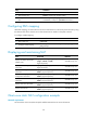
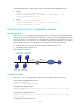
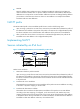
Figure 26 Network diagram
Configuration procedure
# As shown in Figure 26, configure the IP addresses for the interfaces. (Details not shown.)
# Configure a one-to-one static NAT mapping.
<Firewall> system-view
[Firewall] nat static 10.110.10.8 202.38.1.100
# Enable static NAT on interface GigabitEthernet 0/2.
[Firewall] interface gigabitethernet 0/2
[Firewall-GigabitEthernet0/2] nat outbound static
[Firewall-GigabitEthernet0/2] quit
Dynamic NAT configuration example
Network requirements
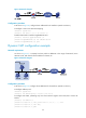
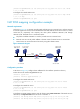
As shown in Figure 27, a company has three public IP addresses in the range of 202.38.1.1/24 to
202.38.1.3/24, and internal network address 10.110.0.0/16.
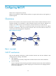
Figure 27 Network diagram
Configuration procedure
# As shown in Figure 27, configure the IP addresses for the interfaces. (Details not shown.)
# Configure address pool 1.
<Firewall> system-view
[Firewall] nat address-group 1 202.38.1.2 202.38.1.3
# Configure ACL 2001, permitting only users from network segment 10.110.10.0/24 to access the
Internet.
[Firewall] acl number 2001
[Firewall-acl-basic-2001] rule permit source 10.110.10.0 0.0.0.255
[Firewall-acl-basic-2001] rule deny
[Firewall-acl-basic-2001] quit