
HP VPN Firewall Appliances NAT and ALG Configuration Guide

44
# Associate the prefix with the address pool for IPv6 hosts accessing IPv4 hosts.
[Firewall] natpt v6bound dynamic prefix 3001:: address-group 1
2. Configure Router A on the IPv4 side:
# Configure an IP address for GigabitEthernet 0/1.
<RouterA> system-view
[RouterA] interface gigabitethernet 0/1
[RouterA-GigabitEthernet0/1] ip address 8.0.0.2 255.255.255.0
[RouterA-GigabitEthernet0/1] quit
# Configure a static route to subnet 9.0.0.0/24.
[RouterA] ip route-static 9.0.0.0 24 8.0.0.1
3. Configure Router B on the IPv6 side:
# Enable IPv6.
<RouterB> system-view
[RouterB] ipv6
# Configure an IP address for GigabitEthernet 0/1.
[RouterB] interface gigabitethernet 0/1
[RouterB-GigabitEthernet0/1] ipv6 address 2001::2/64
[RouterB-GigabitEthernet0/1] quit
# Configure a static route to the subnet with the NAT-PT prefix.
[RouterB] ipv6 route-static 3001:: 16 2001::1
Configuring static mappings on the IPv4 side and the IPv6 side
Network requirements
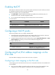
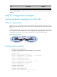
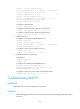
As shown in Figure 33, Router B with IPv6 address 2001::2/64 on an IPv6 network can communicate
with Router A with IPv4 address 8.0.0.2/24 on an IPv4 network.
To meet the preceding requirement, you need to configure Firewall that is deployed between the IPv4
network and IPv6 network as a NAT-PT device, and configure static mappings on the IPv4 side and IPv6
side on Firewall, so that Router A and Router B can communicate with each other.
Figure 33 Network diagram
Configuration procedure
1. Configure Firewall:
# Configure interface addresses and enable NAT-PT on the interfaces.
<Firewall> system-view
[Firewall] ipv6