HP VPN Firewall Appliances System Management and Maintenance Configuration Guide Part number: 5998-4170 Software version: F1000-A-EI/F1000-S-EI (Feature 3726) F1000-E (Release 3177) F5000 (Feature 3211) F5000-S/F5000-C (Release 3808) VPN firewall modules (Release 3177) 20-Gbps VPN firewall modules (Release 3817) Document version: 6PW101-20130923
Legal and notice information © Copyright 2013 Hewlett-Packard Development Company, L.P. No part of this documentation may be reproduced or transmitted in any form or by any means without prior written consent of Hewlett-Packard Development Company, L.P. The information contained herein is subject to change without notice.
Contents Displaying device information ···································································································································· 1 Displaying device information ········································································································································· 2 Displaying system resource state ····································································································································· 3
Displaying the current working directory ············································································································ 25 Changing the current working directory ············································································································· 26 Creating a directory ·············································································································································· 26 Removing a directory ···················
Restoring the next-startup configuration file from a TFTP server ······································································· 61 Deleting the next-startup configuration file ········································································································· 61 Displaying and maintaining a configuration file ······························································································· 62 Configuring the information center ···································
Displaying Displaying Displaying Displaying attack prevention logs ····················································································································· 105 blacklist logs ····································································································································· 105 interzone policy logs ······················································································································· 106 user logs (flow logging
Configuring SNMP traps ············································································································································· 156 Enabling SNMP traps ········································································································································· 156 Configuring the SNMP agent to send traps to a host ····················································································· 157 Displaying and maintaining SNMP ········
Configuration procedure ···································································································································· 201 Configuring virtual firewalls ··································································································································· 203 Overview······································································································································································· 203 VD b
Configuring the ACS URL ··································································································································· 235 Configuring the ACS username and password ······························································································· 235 Configuring CPE attributes ·········································································································································· 236 Configuring the CPE username and passwor
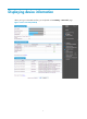
Displaying device information When you log in to the Web interface, you are placed on the Summary > Device Info page.
Figure 2 Device overview (F5000-S) Select the refresh mode from the Refresh Period list. • If you select a specific period, the system periodically refreshes the Device Info page. • If you select Manual, click Refresh to refresh the page. Displaying device information Table 1 Field description Field Description Device Name Device name. Product Information Product information. Device Location Location of the device. Contact Information Contact information for device maintenance.
Displaying system resource state Table 2 Field description Field Description CPU Usage Real-time CPU usage. Flow Engine Usage Real-time flow engine usage. Memory Usage Real-time memory usage. Temperature Temperature of the device. Active Sessions on Current Virtual Device Active sessions on the current virtual device. All Active Sessions All the active sessions on the device. The display for system resource states depends on your device model.
Hardware Feature compatible F5000-S/F5000-C No VPN firewall modules No 20-Gbps VPN firewall modules Yes Table 4 Field description Field Description Time Time when the system logs are generated. Level Level of the system logs. Description Contents of the system logs. The Device Info page displays five recent system logs.
Using ping, tracert, and system debugging Use the ping, tracert, and system debugging utilities to test network connectivity and identify network problems. Ping The ping utility sends ICMP echo requests (ECHO-REQUEST) to the destination device. Upon receiving the requests, the destination device responds with ICMP echo replies (ECHO-REPLY) to the source device.
Figure 4 Ping operation result Configuring ping at the CLI Using a ping command to test network connectivity Execute ping commands in any view. Task Command Remarks • For an IPv4 network: Test the network connectivity to an IP address.
Figure 5 Network diagram 2. Configuration procedure # Use the ping command on Device A to test connectivity to Device C. ping 1.1.2.2 PING 1.1.2.2: 56 data bytes, press CTRL_C to break Reply from 1.1.2.2: bytes=56 Sequence=1 ttl=254 time=205 ms Reply from 1.1.2.2: bytes=56 Sequence=2 ttl=254 time=1 ms Reply from 1.1.2.2: bytes=56 Sequence=3 ttl=254 time=1 ms Reply from 1.1.2.2: bytes=56 Sequence=4 ttl=254 time=1 ms Reply from 1.1.2.2: bytes=56 Sequence=5 ttl=254 time=1 ms --- 1.1.2.
Reply from 1.1.2.2: bytes=56 Sequence=4 ttl=254 time=1 ms Record Route: 1.1.2.1 1.1.2.2 1.1.1.2 1.1.1.1 Reply from 1.1.2.2: bytes=56 Sequence=5 ttl=254 time=1 ms Record Route: 1.1.2.1 1.1.2.2 1.1.1.2 1.1.1.1 --- 1.1.2.2 ping statistics --5 packet(s) transmitted 5 packet(s) received 0.00% packet loss round-trip min/avg/max = 1/11/53 ms The test procedure with the ping –r command (see Figure 5) is as follows: 1.
Figure 6 Traceroute operation Tracert uses received ICMP error messages to get the IP addresses of devices. As shown in Figure 6, tracert works as follows: 1. The source device (Device A) sends a UDP packet with a TTL value of 1 to the destination device (Device D). The destination UDP port is not used by any application on the destination device. 2.
Figure 7 Trace route configuration page 3. Enter the IP address or host name of the destination device in the Trace Route field, 4. Click Start. 5. View the result in the Summary box, as shown in Figure 8. Figure 8 Trace route operation result Configuring tracert at the CLI Prerequisites Before you use a tracert command, perform the tasks in this section.
• Enable sending of ICMP timeout packets on the intermediate devices (devices between the source and destination devices). If the intermediate devices are HP devices, execute the ip ttl-expires enable command on the devices. For more information about this command, see System Management and Maintenance Command Reference. • Enable sending of ICMP destination unreachable packets on the destination device. If the destination device is an HP device, execute the ip unreachables enable command.
displayed on a terminal (including console or VTY). You can also send debugging information to other destinations. For more information, see "Configuring the information center." Figure 9 Relationship between the protocol and screen output switch Debugging a feature module Output from debugging commands is memory intensive. To guarantee system performance, enable debugging only for modules that are in an exceptional condition.
Step 4. Command display debugging [ interface interface-type interface-number ] [ module-name ] [ | { begin | exclude | include } regular-expression ] Display the enabled debugging functions. Remarks Optional. Available in any view. Ping and tracert example Network requirements As shown in Figure 10, Firewall A failed to Telnet Firewall B. Determine whether Firewall A and Firewall B can reach each other. If they cannot reach each other, locate the failed nodes in the network.
3 * * * 4 * * * 5 The output shows that Firewall A and Firewall B cannot reach each other, Firewall A and Device can reach each other, and an error occurred on the connection between Device and Firewall B. # Use the debugging ip icmp command on Firewall A and Firewall B to verify that they can send and receive the specific ICMP packets. Or use the display ip routing-table command to verify the availability of active routes between Firewall A and Firewall B.
Optimizing IP performance Optimization IP performance can be configured only at the CLI. This chapter describes multiple features for IP performance optimization. Enabling receiving and forwarding of directed broadcasts to a directly connected network A directed broadcast packet is destined for all hosts on a specific network. In the destination IP address of the directed broadcast, the network ID identifies the target network, and the host ID is made up of all ones.
To enable the device to forward directed broadcasts: Step Command Remarks 1. Enter system view. system-view N/A 2. Enter interface view. interface interface-type interface-number N/A 3. Enable the interface to forward directed broadcasts. ip forward-broadcast [ acl acl-number ] Disabled by default. Receiving and forwarding directed broadcasts configuration example Network requirements As shown in Figure 11, the default gateway of the host is the IP address 1.1.1.
[FirewallB-GigabitEthernet0/2] ip address 2.2.2.1 24 [FirewallB-GigabitEthernet0/2] quit After the configurations, if you ping the subnet-directed broadcast address (2.2.2.255) on the host, the ping packets can be received by the interface GigabitEthernet 0/2 of Firewall B. However, if you cancel the ip forward-broadcast configuration on any firewall, the ping packets cannot be received by the interface GigabitEthernet 0/2 of Firewall B.
2. A router that fails to forward the packet because it exceeds the MTU on the outgoing interface discards the packet and returns an ICMP error message, which contains the MTU of the outgoing interface. 3. Upon receiving the ICMP message, the TCP source device calculates the current path MTU of the TCP connection. 4. The TCP source device sends subsequent TCP segments that each are smaller than the MSS (MSS =path MTU–IP header length–TCP header length).
• synwait timer—When sending a SYN packet, TCP starts the synwait timer. If no response packet is received within the synwait timer interval, the TCP connection cannot be created. • finwait timer—When a TCP connection is changed into FIN_WAIT_2 state, the finwait timer is started. { { If no FIN packet is received within the timer interval, the TCP connection is terminated. If a FIN packet is received, the TCP connection state changes to TIME_WAIT.
{ { If the device finds that the destination of a packet is not itself and the TTL field of the packet is 1, it sends a "TTL timeout" ICMP error message. When the device receives the first fragment of an IP datagram whose destination is the device itself, it starts a timer. If the timer times out before all fragments of the datagram are received, the device sends a "reassembly timeout" ICMP error packet.
Step Command Remarks • Enable sending ICMP redirect packets: ip redirects enable 2. Enable sending ICMP error packets. • Enable sending ICMP timeout packets: ip ttl-expires enable • Enable sending ICMP destination unreachable packets: ip unreachables enable Disabled by default. When sending ICMP timeout packets is disabled, the device does not send "TTL timeout" ICMP error packets. However, "reassembly timeout" error packets are sent correctly.
Managing the file system You can manage the file system only at the CLI. Feature and hardware compatibility Hardware Storage medium F1000-A-EI/F1000-S-EI flash0 F1000-E cfa0 F5000 cfa0 F5000-S/F5000-C cfa0 VPN firewall modules cfa0 20-Gbps VPN firewall modules cfa0 All examples in this chapter use the storage medium cfa0. Overview This chapter describes how to manage the device's file system, including the storage media, directories, and files.
File name formats When you specify a file, enter the file name in one of the formats shown in Table 5. When you specify a directory, enter the directory in one of the formats that contains the path argument. Table 5 File name formats Format Description Length Example file-name Specifies a file in the current working directory. 1 to 91 characters a.cfg indicates a file named a.cfg in the current working directory. 1 to 135 characters test/a.cfg indicates a file named a.
Displaying the contents of a file Perform this task in user view. Task Command Remarks Display the contents of a file. more file-url [ | { begin | exclude | include } regular-expression ] Only text files can be displayed. Renaming a file Perform this task in user view. Task Command Rename a file. rename fileurl-source fileurl-dest Copying a file Perform this task in user view. Task Command Copy a file. copy fileurl-source fileurl-dest Moving a file Perform this task in user view.
Task Command Delete a file permanently. delete /unreserved file-url Emptying the recycle bin Step 1. 2. Command Remarks Enter the original working directory of the file to be deleted in user view. cd { directory | .. | / } Skip this step if the original directory of the file is the current working directory. Empty the recycle bin.
Changing the current working directory Perform this task in user view. Task Command Change the current working directory. cd { directory | .. | / } Creating a directory Perform this task in user view. Task Command Create a directory. mkdir directory Removing a directory To remove a directory, you must delete all files and subdirectories in this directory. To delete a file, use the delete command. To delete a subdirectory, use the rmdir command.
Task Command Remarks Repair a storage medium. fixdisk medium-name N/A Format a storage medium. format medium-name [ FAT16 | FAT32 ] The FAT16 and FAT32 keywords are not supported on the Flash. Partitioning a CF card A CF card can be divided into several different logical devices, or, partitions. Operations on a partition do not affect the other partitions.
Hardware Feature compatible F1000-A-EI/F1000-S-EI Yes F1000-E No F5000 No F5000-S/F5000-C No VPN firewall modules No 20-Gbps VPN firewall modules No The physical space of the NAND Flash memory is divided into multiple blocks, each of which is subdivided into multiple pages. The NAND Flash memory is erased on a block basis and read on a page basis; the memory spaces are allocated on a page basis. Displaying and repairing bad blocks Bad block ratio varies with products of different vendors.
To execute a batch file: Step Command 1. Enter system view. system-view 2. Execute a batch file. execute filename Setting the file system operation mode The file systems support the following operation modes: • alert—The system warns you about operations that might cause problems such as file corruption and data loss. To prevent incorrect operations, use the alert mode. • quiet—The system does not prompt for any operation confirmation.
# Create new folder mytest in the test directory. cd test mkdir mytest %Created dir cfa0:/test/mytest. # Display the current working directory. pwd cfa0:/test # Display the files and the subdirectories in the test directory. dir Directory of cfa0:/test/ 0 drw- - Feb 16 2006 15:28:14 2540 KB total (2519 KB free) # Return to the upper directory. cd .. # Display the current working directory.
Upgrading software You can use the CLI, BootWare menus, or Web interface to upgrade software. This chapter describes how to upgrade software from the CLI and the Web interface. The following matrix shows the storage media available on different firewalls and firewall modules: Hardware Storage medium F1000-A-EI/F1000-S-EI flash0 F1000-E cfa0 F5000 cfa0 F5000-S/F5000-C cfa0 VPN firewall modules cfa0 20-Gbps VPN firewall modules cfa0 All examples in this chapter use the storage medium cfa0.
Figure 12 System startup process Start Select the Reboot option to reboot the device BootWare runs Press Ctrl+B Yes Enter BootWare menus to upgrade BootWare or system software No Run system software image Enter CLI Finish FIPS compliance The device supports the FIPS mode that complies with NIST FIPS 140-2 requirements. Support for features, commands, and parameters might differ in FIPS mode and non-FIPS mode. For more information about FIPS mode, see Access Control Configuration Guide.
Upgrading method Upgrading from the BootWare menus Software types Remarks • BootWare image • System software Use this method when the device cannot start up correctly. For information about this upgrading method, see the release notes for your device. image Upgrading BootWare You can upgrade the BootWare image only from the CLI. To upgrade the BootWare image: Step 1. 2. Command Use FTP or TFTP to transfer the BootWare image to the root directory of the storage medium.
Upgrading system software in the Web interface IMPORTANT: Upgrading software takes some time. During software upgrade, do not perform any operation on the Web interface. Otherwise, the upgrade might be interrupted. To upgrade software: 1. Select Device Management > Software Upgrade from the navigation tree. Figure 13 Software upgrade configuration page 2. Configure upgrade parameters as described in Table 6. 3. Click Apply.
Upgrading system software at the CLI Step Command Remarks The image file must be saved in the root directory for a successful upgrade. Use FTP or TFTP to transfer the system software image to the root directory of the storage medium. See "Configuring FTP" or "Configuring TFTP." 2. Specify the file as the startup system software image in user view.
Patch states A patch is in IDLE, DEACTIVE, ACTIVE, or RUNNING state, depending on the patch manipulation command. Patch manipulation commands include patch load (load), patch active (run temporarily), patch run (confirm running), patch deactive (stop running), patch delete (delete), patch install (install), and undo patch install (uninstall). For example, if you execute the patch active command, patches in DEACTIVE state change to the ACTIVE state.
Figure 15 Patches that are not loaded to the patch memory area DEACTIVE state Patches in DEACTIVE state have been loaded to the patch memory area but have not yet run in the system. Suppose that the patch file you are loading has seven patches. After the seven patches successfully pass the version check and CRC check, they are loaded to the patch memory area and are in DEACTIVE state. In the patch memory area, patch states are as shown in Figure 16.
Figure 17 Patches are activated RUNNING state After you confirm ACTIVE patches, their states change to RUNNING and persist after a reboot. In contrast to ACTIVE patches, RUNNING patches continue to take effect after a reboot. For example, if you confirm the first three patches in Figure 17, their state changes from ACTIVE to RUNNING, and the RUNNING state persists after a reboot. Figure 18 shows the patch states in the system.
• Make sure each patch file you are installing matches the device model and software version. • Save patch files or patch package files to the root directory of the device's storage medium. If the storage medium has been partitioned, save the files to the root directory of the first partition. • Correctly name a patch file in the patch_PATCH-FlAG suffix.bin format.
Step-by-step patch installation task list Task Remarks Optional. Configuring the patch file location To install a patch package, skip this step. Loading a patch file Required. Activating patches Required. Confirming ACTIVE patches Optional. Configuring the patch file location For reliable patch loading, HP recommends saving patch files to the root directory of the storage medium. If the patch file is saved in the root directory, you do not need to specify the patch location.
Activating patches Activating a patch changes its state to ACTIVE. An ACTIVE patch runs in memory until a reboot occurs. To have a patch continue to run after a reboot, you must change its state to RUNNING. To activate patches: Step Command 1. Enter system view. system-view 2. Activate patches. patch active [ patch-number ] Confirming ACTIVE patches To have an ACTIVE patch continue to run after a reboot, perform the task in this section.
Displaying and maintaining software upgrade Task Command Remarks Display information about the system software image. display boot-loader [ | { begin | exclude | include } regular-expression ] Available in any view. Display information about the patch package. display patch [ | { begin | exclude | include } regular-expression ] Available in any view. Display the patch information. display patch information [ | { begin | exclude | include } regular-expression ] Available in any view.
[FTP-Server-luser-aaa] password cipher hello [FTP-Server-luser-aaa] service-type ftp [FTP-Server-luser-aaa] authorization-attribute work-directory cfa0:/aaa 2. Configure the firewall: # Log in to the FTP server. ftp 2.2.2.2 Trying 2.2.2.2 ... Press CTRL+K to abort Connected to 2.2.2.2. 220 WFTPD 2.0 service (by Texas Imperial Software) ready for new user User(2.2.2.2:(none)):aaa 331 Give me your password, please Password: 230 Logged in successfully # Download new-config.
Configuration procedure 1. Configure the TFTP server (the configuration varies with server vendors): # Enable the TFTP server function. (Details not shown.) # Save the patch file patch_xxx.bin to the working directory on the TFTP server. (Details not shown.) 2. Configure the firewall: # Use the save command to save the running configuration. (Details not shown.) # Examine the storage medium on the firewall for space insufficiency. If the free space is not sufficient for the patches, delete unused files.
Dealing with password loss CAUTION: Dealing with console login password loss and user privilege level password loss from BootWare menus is disruptive. How to deal with console login password loss and user privilege level password loss depends on the state of password recovery capability (see Figure 21).
Figure 21 Dealing with password loss Password lost No Yes Password recovery capability enabled? Console login password lost User privilege level password lost Reboot to access EXTENDBOOTWARE menu Reboot to access EXTENDBOOTWARE menu Reboot to access EXTENDBOOTWARE menu Enter 6 to skip console login authentication Enter 8 to clear user privilege level password Enter 5 to restore factory defaults Reboot Configure new passwords in system view Save the running configuration Examining the state of p
cfa0 Size : 247MB CPLD_A Version : 1.0 CPLD_B Version : 1.0 PCB Version : Ver.A BootWare Validating... Press Ctrl+B to enter extended boot menu... BootWare password: Not required. Please press Enter to continue. 2. Press Ctrl + B immediately after the "Press Ctrl+B to enter extended boot menu..." prompt message appears. The following prompt message appears: Please press Enter to continue 3. Press Enter to access the EXTEND-BOOTWARE menu.
Enter < Storage Device Operation > to select device.
Dealing with user privilege level password loss when password recovery capability is enabled 1. Reboot the device to access the EXTEND-BOOTWARE menu, and then enter 8. Password recovery capability is enabled. Note: The current operating device is cfa0 Enter < Storage Device Operation > to select device.
Note: The current operating device is cfa0 Enter < Storage Device Operation > to select device.
Managing configuration files You can use the CLI, BootWare menus, or Web interface to manage configuration files. This chapter explains how to manage configuration files from the CLI and the Web interface. Overview You can save the running configuration to a configuration file so the configuration takes effect after you reboot the device. You can also back up the configuration file on to a host and download the file to the device as needed.
Configuration file content organization and format IMPORTANT: To run on the device, a configuration file must meet the content and format requirements of the device. To ensure a successful configuration load at startup, use a configuration file created on the device. If you edit the configuration file, make sure all edits are compliant with the requirements of the device. A configuration file must meet the following requirements: • All commands are saved in their complete form.
• Only one administrator can save the configuration at a moment. If one administrator saves the configuration while the system is saving the configuration as required by another administrator, the system prompts the second administrator to try later. Procedures This module supports saving the configuration in either of the following modes: fast or common. To save the configuration in fast mode, click the Save button at the upper right of the auxiliary area.
Figure 23 Backing up the configuration 3. Click the upper Backup button. A file download dialog box appears. 4. Select to view the .cfg file or to save the file to the local host. 5. Click the lower Backup button. A file download dialog box appears. 6. Select to view the .xml file or to save the file to the local host. Restoring the next-startup configuration file Configuration restoration allows you to: • Upload the .cfg file on the host of the administrator to the device for the next startup.
4. Click Apply. Resetting the configuration This operation disables the next-startup configuration file to serve for the next startup, restores the device's factory defaults, and reboots the device. To reset the configuration: 1. Select Device Management > Maintenance from the navigation tree. 2. Click the Initialize tab. Figure 25 Resetting the configuration 3. To delete signature files, select Delete signature files. 4.
Figure 26 Importing the configuration 3. Click Browse. 4. Select the .cfg file to be imported as prompted. 5. Click Apply. Managing configuration files at the CLI Saving the running configuration To make configuration changes take effect at the next startup, save the running configuration to the startup configuration file to be used at the next startup before the device reboots. Complete the following tasks to save the running configuration: Task Remarks Optional.
Saving running configuration by using different methods When saving the running configuration to a configuration file, you can specify the file as the next-startup configuration file. If you are specifying the file as the next-startup configuration file, use one of the following methods to save the configuration: • Fast mode—Use the save command without the safely keyword. In this mode, the device directly overwrites the target next-startup configuration file.
The configuration archive function was developed to facilitate configuration rollback. This function enables the system to automatically save the running configuration at regular intervals. Configuration task list Task Remarks Configuring configuration archive parameters Required. • Enabling automatic configuration archiving • Manually archiving running configuration Required. Performing configuration rollback Required. Use either method.
Step Command Remarks Optional. Set the maximum number of configuration archives. 4. archive configuration max file-number The default number is 5. Change the setting depending on the available storage space. Enabling automatic configuration archiving To avoid decreasing system performance, follow these guidelines when you configure automatic configuration archiving: • If the device configuration does not change frequently, manually archive the running configuration as needed.
The replacement configuration file is not encrypted. • To perform a configuration rollback: Step Command 1. Enter system view. system-view 2. Perform configuration rollback. configuration replace file filename The configuration rollback function might fail to reconfigure some commands in the running configuration for one of the following reasons: • A command cannot be undone, because prefixing the undo keyword to the command does not result in a valid undo command.
Step Back up the next-startup configuration file to a TFTP server in user view. 2. Command Remarks backup startup-configuration to dest-addr [dest-filename ] This command is not supported in FIPS mode. Restoring the next-startup configuration file from a TFTP server To download a configuration file from a TFTP server to the device and specify the file as the next-startup configuration file, perform the task in this section.
Displaying and maintaining a configuration file Task Command Remarks Display information about configuration rollback. display archive configuration [ | { begin | exclude | include } regular-expression ] Available in any view. Display the running configuration. display current-configuration [ configuration [ configuration ] | interface [ interface-type [ interface-number ] ] | exclude modules ] [ by-linenum ] [ | { begin | exclude | include } regular-expression ] Available in any view.
Configuring the information center The information center can be configured only at the CLI. Overview The information center collects and classifies system information as follows: • Receives system information including log, trap, and debug information from source modules. • Outputs the information to different information channels, according to output rules. • Outputs information to different destinations, based on channel-to-destination associations.
Table 7 System information levels Severity Severity value Description Corresponding keyword in commands Emergency 0 The system is unusable. For example, the system authorization has expired. emergencies Alert 1 Action must be taken immediately to solve a serious problem. For example, traffic on an interface exceeds the upper limit. alerts Critical 2 Critical condition. For example, the device temperature exceeds the upper limit, the power module fails or the fan tray fails.
Table 8 Default information channels and output destinations Channel number Default channel name Default output destination System information received by default 0 console Console Log, trap and debug information 1 monitor Monitor terminal Log, trap and debug information 2 loghost Log host Log, trap and debug information 3 trapbuffer Trap buffer Trap information 4 logbuffer Log buffer Log information 5 snmpagent SNMP module Trap information 6 channel6 Web interface Log informa
Destination Source modules Log file All supported modules Trap Log Debug Status Severity Status Severity Status Severity Enabled Debug Enabled Debug Disabled Debug System information formats The following matrix shows support for outputting system information in china-unicom-nat444 or china-telecom format to a log host on different firewalls and firewall modules: Hardware Outputting system information in china-unicom-nat444 or china-telecom format to a log host F1000-A-EI/F1000-S-EI N
Output destination Format Example • HP format: • HP format: timestamp Sysname %%vvmodule/level /digest: source content <189>Oct 9 14:59:04 2009 Sysname %%10SHELL/5/SHELL_LOGIN(l): VTY logged in from 192.168.1.21.
Field Description • If the system information that is sent to a log host is in the UNICOM format, and Sysname (host name or host IP address) the info-center loghost source command is configured, or the vpn-instance vpn-instance-name option is provided in the info-center loghost command, the sysname field is displayed as the IP address of the device that generated the system information.
Table 12 Timestamp precisions and configuration commands Item Destined to the log host Destined to the console, monitor terminal, log buffer, and log file Precision Seconds Milliseconds Command used to set the timestamp format info-center timestamp loghost info-center timestamp Table 13 Description of the timestamp parameters Timestamp parameters boot date Description Example Time since system startup, in the format of xxx.yyy.
Task Remarks Outputting system information to a log host Optional. Outputting system information to the trap buffer Optional. Outputting system information to the log buffer Optional. Outputting system information to the SNMP module Optional. Outputting system information to the Web interface Optional. Saving system information to the log file Optional. Managing security logs and the security log file Optional. Enabling synchronous information output Optional.
Step Command Remarks • Enable the display of debug information on the console: terminal debugging 9. Enable the display of system information on the console. • Enable the display of log information on the console: terminal logging • Enable the display of trap Optional. By default, the console displays log and trap information, and discards debug information.
Step Command Remarks The default setting is disabled. 8. Enable system information output to the monitor terminal. terminal monitor You must execute this command before you can enable the display of debugging, log, and trap information on the monitor terminal. • Enable the display of debug information on the monitor terminal: terminal debugging 9. Enable the display of system information on the monitor terminal.
Step Command Remarks • Set the format to unicom: info-center format unicom • Set the format to china-telecom: 7. Set the system information format. info-center format china-telecom Optional. The default setting is HP. • Set the format to china-unicom-nat444: info-center format china-unicom-nat444 • Set the format to HP: The china-telnetcom and china-unicom-nat444 formats are available only for NAT444. For more information about NAT444, see NAT and ALG Configuration Guide.
Step Command 2. Enable the information center. info-center enable 3. Specify a name for a channel identified by its number. info-center channel channel-number name channel-name Configure an output channel for the trap buffer and set the buffer size. info-center trapbuffer [ channel { channel-number | channel-name } | size buffersize ] * 5. Configure an output rule for the trap buffer.
Step Command 5. Configure an output rule for the log buffer. info-center source { module-name | default } channel { channel-number | channel-name } [ debug { level severity | state state } * | log { level severity | state state } * | trap { level severity | state state } * ] * 6. Configure the timestamp format. info-center timestamp { debugging | log | trap } { boot | date | none } Remarks Optional. See "Default output rules of system information." Optional.
Outputting system information to the Web interface The Web interface only receives log information, and discards trap and debug information. This feature allows you to control whether to output system information to the Web interface and, if so, which system information can be output to the Web interface. The Web interface provides abundant search and sorting functions.
Hardware Outputting system information to the log file 20-Gbps VPN firewall modules Yes Perform this task to save system information from the log buffer to a log file. You can specify the interval to save system information, or you can manually save system information. After saving log information from the log buffer to a log file, the system clears the log buffer. The device supports only one log file. The log file has a specific capacity.
Managing security logs and the security log file Security logs are very important for locating and troubleshooting network problems. Generally, security logs are output together with other logs. It is difficult to identify security logs among all logs. To solve this problem, you can save security logs into a security log file without affecting the current log output rules. The security log file is managed by a privileged user.
Step 5. Set the maximum size of the security log file. Command Remarks info-center security-logfile size-quota size Optional. The default setting is 1 MB. Optional. 6. Set the alarm threshold of the security log file usage. info-center security-logfile alarm-threshold usage 80 by default. That is, when the usage of the security log file reaches 80%, the system informs the user.
Task Command Remarks • Display the contents of the specified file: more file-url • Display information about all files and folders: dir [ /all ] [ file-url ] • Create a folder in a specified directory on the storage medium: mkdir directory • Change the current working directory: cd { directory | .. | / } • Display the current path: pwd Optional. • Copy a file: Perform these operations to the security log file.
Task Command Remarks • Establish a connection to an IPv4 SFTP server and enter SFTP client view: sftp server [ port-number ] [ vpn-instance vpn-instance-name ] [ prefer-compress { zlib | zlib-openssh } | prefer-ctos-cipher { 3des | aes128 | des } | prefer-ctos-hmac { md5 | md5-96 | sha1 | sha1-96 } | prefer-kex { dh-group-exchange | dh-group1 | dh-group14 } | prefer-stoc-cipher { 3des | aes128 | des } | prefer-stoc-hmac { md5 | md5-96 | sha1 | sha1-96 } ] * • Establish a connection to an (Optional) Uplo
output and a command prompt in command editing mode, or a [Y/N] string in interaction mode so you can continue your operation from where you were stopped. If system information, such as log information, is output before you input any information under the current command line prompt, the system does not display the command line prompt after the system information output.
Displaying and maintaining information center Task Command Remarks Display information about information channels. display channel [ channel-number | channel-name ] [ | { begin | exclude | include } regular-expression ] Available in any view. Display information center configuration information. display info-center [ | { begin | exclude | include } regular-expression ] Available in any view.
system-view [Firewall] info-center enable # Use channel console to output log information to the console. (This step is optional because it is the default setting.) [Firewall] info-center console channel console # Disable all modules from outputting log, trap, and debug information to channel console.
# Disable all modules from outputting log, trap, and debug information to channel loghost. [Firewall] info-center source default channel loghost debug state off log state off trap state off To avoid output of unnecessary information, disable all modules from outputting log, trap, and debug information to the specified channel (loghost in this example) before you configure the output rule.
Outputting log information to a Linux log host Network requirements Configure the firewall to send log information that has a severity level of at least informational to the Linux log host at 1.2.0.1/16. Figure 30 Network diagram Configuration procedure Before the configuration, make sure the firewall and the log host can reach each other. (Details not shown.) 1. Configure the firewall: # Enable the information center. system-view [Firewall] info-center enable # Specify the host 1.2.0.
NOTE: Be aware of the following issues while editing file /etc/syslog.conf: • Comments must be on a separate line and must begin with a pound sign (#). • No redundant spaces are allowed after the file name. • The logging facility name and the information level specified in the /etc/syslog.conf file must be identical to those configured on the firewall by using the info-center loghost and info-center source commands. Otherwise, the log information might not be output properly to the log host. d.
{ { 2. Create a local user seclog with the password 123123123123, and authorize this user as the security log administrator. That is, use the authorization-attribute command to set the user privilege level to 3 and specify the user role as security audit. In addition, specify the service types that the user can use by using service-type.
Password: # Display the summary of the security log file. display security-logfile summary Security-log is enabled. Security-log file size quota: 1MB Security-log file directory: cfa0:/seclog Alarm-threshold: 80% Current usage: 0% Writing frequency: 1 hour 0 min 0 sec The output shows that the directory for saving the security log file is cfa0:/seclog. # Change the directory where the security log file is saved to cfa0:/securitylog. mkdir securitylog .
Managing logs This chapter describes how to manage various types of logs. Configuring syslog Syslog can be configured only in the Web interface. The syslog module allows you to set parameters for the information center. The information center classifies and manages system information and it can output log information to the Web interface and log hosts. To configure syslog: 1. Select Log Report > Syslog from the navigation tree to enter the page as shown in Figure 32.
Figure 32 Syslog 2. Configure syslog settings as described in Table 14. 3. Click Apply. Table 14 Configuration items Item Description Log Buffer Size Set the number of syslogs that can be stored in the log buffer. Syslogs that can be stored in the log buffer include system logs, connection limit logs, attack prevention logs, blacklist logs, and interzone policy logs. The value range and default setting depend on the device model. For more information, see Table 15.
Item Description Log Host 1 Log Host IP Address Log Host 2 Log Host 3 Log Host 4 Set the address (IPv4 address, host name, or IPv6 address), port number and the VPN instance (this option is available only when you specify a log host with an IPv4 address or a host name) of the syslog log host. You can report log information to log hosts in the format of syslog. You can specify up to four syslog log hosts. Select the refresh mode for the log report Web page.
Table 16 Packet format in user logging version 1.0 Field Description SourceIP Source IP address. DestIP Destination IP address. SrcPort TCP/UDP source port number. DestPort TCP/UDP destination port number. StartTime Start time of the flow, in seconds, counted from 1970/1/1 0:0. EndTime End time of the flow, in seconds, counted from 1970/1/1 0:0. Prot Protocol. Operator Indicates the reason why the flow ended. Reserved For future applications.
Configuring user logging in the Web interface Configuring user logging To configure user logging: 1. Select Log Report > Userlog from the navigation tree to enter the page as shown in Figure 33. Figure 33 User logging 2. Configure user logging settings as described in Table 18. 3. Click Apply. Table 18 Configuration items Item Description Set the user logging version, 1.0 or 3.0.
Item Description Set the source IP address of user logging packets. Source IP Address of Packets After you specify the source IP address, when Device A sends user logs to Device B, it uses the specified IP address instead of the actual egress address as the source IP address of the packets. In this way, although Device A sends out packets to Device B through different ports, Device B can judge whether the packets are sent from Device A according to their source IP addresses.
Figure 34 Viewing user logging statistics Clearing user logs and user logging statistics 1. Select Log Report > Userlog from the navigation tree to enter the page as shown in Figure 33. 2. Click the Statistics expansion button on the page to display the information as shown in Figure 34. 3. Click Reset. The system clears all user logging statistics for the device and user logs in the cache. Configuring user logging at the CLI At the CLI, user logging is also known as "flow logging.
Step Command Remarks Optional. The default version is 1.0. Configure the user logging version. 2. userlog flow export version version-number Although the device supports two versions, only one can be active at one time. Therefore, if you configure the user logging version multiple times, the most recent configuration takes effect. Configuring the source address for user logs A source IP address is usually used to uniquely identify the sender of a packet. Suppose Device A sends flow logs to Device B.
Exporting user logs User logs can be exported in the following ways: • User logs can be encapsulated into UDP packets and sent to an IPv4 log server or an IPv6 log server. The log server analyzes user logs and displays them by class, thus realizing remote monitoring. • User logs in the format of system information are exported to the information center of the device. You can set the output destinations of the user logs by setting the output parameters of the system information.
Displaying and maintaining user logging Task Command Remarks Display the configuration and statistics about user logging. display userlog export [ | { begin | exclude | include } regular-expression ] Available in any view. Clear statistics about user logging. reset userlog flow export Available in user view. Clear user logs in the cache. reset userlog flow logbuffer Available in user view.
Export Version 3 logs to log server : enabled Source address of exported logs : 2.2.2.2 Address of log server : 1.2.3.6 (port: 2000) total Logs/UDP packets exported : 112/87 Logs in buffer : 6 Troubleshooting user logging Symptom 1: No user log is exported • Analysis: No export approach is specified. • Solution: Configure user logging to export user logs to the information center or to the log server.
Task Remarks Required. Configure the time threshold or/and traffic threshold for session logging, and enable or disable log output for session creation and deletion. Configuring global parameters for session logging By default, both the time threshold and traffic threshold are 0, meaning that no session logging entries are output.
Item Description Specify the ACL for filtering log entries, and only log entries permitted by the ACL will be output. ACL The rules of the specified ACL can be configured on the page entered by selecting Firewall > ACL. Configuring global parameters for session logging 1. Select Log Report > Session Log > Global Setup from the navigation tree. The Global Setup page appears, as shown in Figure 38. Figure 38 Global configuration page 2.
• System logs. • Connection limit logs. • Attack prevention logs. • Blacklist logs. • Interzone policy logs. • User logs. Except that the user logs can be viewed at both the Web interface and the CLI, all other types of log information can only be viewed in the Web interface. Displaying system logs Select Log Report > Report > System Log from the navigation tree to enter the page as shown in Figure 39. Table 21 describes the configuration items.
Table 22 System log severity level Severity level Description Value Emergency System is unusable. 0 Alert Information that demands prompt reaction. 1 Critical Critical information. 2 Error Error information. 3 Warning Warning information. 4 Notification Normal but significant information. 5 Information Informational information to be recorded. 6 Debug Debug information. 7 Note: A smaller value represents a higher severity level.
Item Description ICMP Percentage Percentage of ICMP packets to the total packets. Displaying attack prevention logs Select Log Report > Report > Attack Prevention Log from the navigation tree to enter the page as shown in Figure 41. Table 24 describes the configuration items. Figure 41 Attack prevention log configuration page Table 24 Configuration items Item Description Virtual Device Virtual firewall ID. Time Time when the attack was detected. Type Attack type.
Figure 42 Blacklist log configuration page Table 25 Configuration items Item Description Virtual Device Virtual firewall ID. Time/Date Time when the log was generated. Mode Whether the log is added or removed. Source IP Source IP address. Reason why the source IP address was added to the blacklist: Reason • Auto insert—The source IP address was automatically added to the blacklist by the system. • Manual insert—The source IP address was manually added to the blacklist through the Web interface.
Item Description Start Time Time when the flow was created. End Time Time when the flow was removed. Source Zone Source zone of the flow. Destination Zone Destination zone of the flow. Policy ID ID of the interzone policy that the flow matched. Action Action taken against the flow, permitted or denied. Protocol Type Protocol type of the flow.
Figure 45 User logging 3.0 log report Table 27 User logging 1.0 configuration items Item Description Virtual Device Virtual firewall ID. Time/Date Time and date when the user log was generated. Protocol Type Protocol type of the flow log. Flow information: • If the protocol type is TCP or UDP, the displayed flow information is source IP address:source port-->destination IP address:destination port, for example, 1.1.1.2:1026-->1.1.2.10:69.
Table 28 Flow logging 3.0 configuration items Item Description Time/Date Time and date when the flow log was generated. Protocol Type Protocol type of the flow. Flow information: • If the protocol type is TCP or UDP, the displayed flow information is source IP address:source port-->destination IP address:destination port, for example, 1.1.1.2:1026-->1.1.2.10:69.
Configuring NTP You must synchronize your device with a trusted time source by using the Network Time Protocol (NTP) or changing the system time before you run it on a live network. Various tasks, including network management, charging, auditing, and distributed computing depend on an accurate system time setting, because the timestamps of system messages and logs use the system time. Overview NTP is typically used in large networks to dynamically synchronize time among network devices.
How NTP works Figure 46 shows how NTP synchronizes the system time between two devices, in this example, Device A and Device B. Assume that: • Prior to the time synchronization, the time of Device A is set to 10:00:00 am and that of Device B is set to 11:00:00 am. • Device B is used as the NTP server. Device A is to be synchronized to Device B. • It takes 1 second for an NTP message to travel from Device A to Device B, and from Device B to Device A.
NTP message format All NTP messages mentioned in this document refer to NTP clock synchronization messages. NTP uses two types of messages: clock synchronization messages and NTP control messages. NTP control messages are used in environments where network management is needed. Because NTP control messages are not essential for clock synchronization, they are not described in this document. A clock synchronization message is encapsulated in a UDP message, as shown in Figure 47.
• Stratum—An 8-bit integer that indicates the stratum level of the local clock, taking the value of 1 to 16. Clock precision decreases from stratum 1 through stratum 16. A stratum 1 clock has the highest precision, and a stratum 16 clock is not synchronized. • Poll—An 8-bit signed integer that indicates the maximum interval between successive messages, which is called the poll interval. • Precision—An 8-bit signed integer that indicates the precision of the local clock.
(server mode). Upon receiving the replies from the servers, the client performs clock filtering and selection and synchronizes its local clock to that of the optimal reference source. In client/server mode, a client can be synchronized to a server, but not vice versa. Symmetric peers mode Figure 49 Symmetric peers mode In symmetric peers mode, devices that operate in symmetric active mode and symmetric passive mode exchange NTP messages with the Mode field 3 (client mode) and 4 (server mode).
The client continues listening to broadcast messages and synchronizes its local clock based on the received broadcast messages. Multicast mode Figure 51 Multicast mode In multicast mode, a server periodically sends clock synchronization messages to the user-configured multicast address, or, if no multicast address is configured, to the default NTP multicast address 224.0.1.1, with the Mode field in the messages set to 5 (multicast mode). Clients listen to the multicast messages from servers.
Figure 52 Network diagram Configuring NTP in the Web interface Configuring the network time 1. Select Device Management > System Time from the navigation tree. 2. Click Network Time Protocol. The page for configuring the network time appears. Figure 53 Configuring the network time 3. Configure the network time as described in Table 29. 4. Click Apply. Table 29 Configuration items Item Description Clock status Displays the synchronization status of the system clock.
Item Description Set the IP address of the local clock source to 127.127.1.u, where u represents the NTP process ID in the range of 0 to 3. Local Reference Source • If the IP address of the local clock source is specified, the local clock is used as the reference clock, and thus can provide time for other devices. • If the IP address of the local clock source is not specified, the local clock is not used as the reference clock. Set the stratum level of the local clock.
Network requirements Set the local clock of Device A to the reference clock, with the stratum level 2, and Device B to operate in client mode, and uses Device A as the NTP server. Figure 54 Network diagram Configuration procedure 1. On Device A, configure the local clock as the reference clock, with the stratum level 2: a. Select Device Management > System Time from the navigation tree. b. Click Network Time Protocol. The page for setting up NTP appears. c. Select 127.127.1.
Figure 56 Configuring Device A as the NTP server of Device B 3. Verify the configuration: The output shows that the current system time displayed on the System Time page is the same for Device A and Device B. Configuring NTP at the CLI NTP configuration task list Task Remarks Configuring NTP operation modes Required. Configuring the local clock as a reference source Optional. Configuring optional parameters for NTP Optional. Configuring access-control rights Optional.
Configuring the NTP client/server mode If you specify the source interface for NTP messages by specifying the source interface source-interface option, NTP uses the primary IP address of the specified interface as the source IP address of the NTP messages. A device can act as a server to synchronize other devices only after it is synchronized. If a server has a stratum level higher than or equal to a client, the client does not synchronize to that server.
Configuring the NTP broadcast mode The broadcast server periodically sends NTP broadcast messages to the broadcast address 255.255.255.255. After receiving the messages, the device operating in NTP broadcast client mode sends a reply and synchronizes its local clock. Configure the NTP broadcast mode on both the server and clients.
Step Configure the device to operate in NTP multicast client mode. 3. Command Remarks ntp-service multicast-client [ ip-address ] You can configure up to 1024 multicast clients, of which 128 can take effect at the same time. Command Remarks To configure the multicast server: Step 1. Enter system view. system-view N/A 2. Enter interface view. interface interface-type interface-number This command enters the view of the interface for sending NTP multicast messages. 3.
Configuring optional parameters for NTP This section explains how to configure the optional parameters of NTP. Specifying the source interface for NTP messages If you specify the source interface for NTP messages, the device sets the source IP address of the NTP messages as the primary IP address of the specified interface when sending the NTP messages. NTP packets might not be received because of state changes of an interface on the device.
The following describes how an association is established in different operation modes: • Client/server mode—After you specify an NTP server, the system creates a static association on the client. The server simply responds passively upon the receipt of a message, rather than creating an association (static or dynamic).
Configuration procedure To configure the NTP service access-control right to the local device: Step Command Remarks 1. Enter system view. system-view N/A 2. Configure the NTP service access-control right for a peer device to access the local device. ntp-service access { peer | query | server | synchronization } acl-number The default is peer. Configuring NTP authentication Enable NTP authentication for a system running NTP in a network where there is a high security demand.
Step Associate the specified key with an NTP server. 5. Command Remarks ntp-service unicast-server { ip-address | server-name } authentication-keyid keyid You can associate a non-existing key with an NTP server. To enable NTP authentication, you must configure the key and specify it as a trusted key after associating the key with the NTP server. To configure NTP authentication for a server: Step Command Remarks 1. Enter system view. system-view N/A 2. Enable NTP authentication.
Step Command Remarks By default, no NTP authentication key is configured. 3. Configure an NTP authentication key. ntp-service authentication-keyid keyid authentication-mode md5 [ cipher | simple ] value 4. Configure the key as a trusted key. ntp-service reliable authentication-keyid keyid By default, no authentication key is configured to be trusted. ntp-service unicast-peer { ip-address | peer-name } authentication-keyid keyid You can associate a non-existing key with a passive peer.
Step Configure the key as a trusted key. 4. Command Remarks ntp-service reliable authentication-keyid keyid By default, no authentication key is configured to be trusted. To configure NTP authentication for a broadcast server: Step Command Remarks 1. Enter system view. system-view N/A 2. Enable NTP authentication. ntp-service authentication enable By default, NTP authentication is disabled. 3. Configure an NTP authentication key.
Step Command Remarks 1. Enter system view. system-view N/A 2. Enable NTP authentication. ntp-service authentication enable By default, NTP authentication is disabled. 3. Configure an NTP authentication key. ntp-service authentication-keyid keyid authentication-mode md5 [ cipher | simple ] value 4. Configure the key as a trusted key. ntp-service reliable authentication-keyid keyid By default, no authentication key is configured to be trusted. 5. Enter interface view.
Figure 57 Network diagram Configuration procedure 1. Set the IP address for each interface as shown in Figure 57. (Details not shown.) 2. Configure Device A: # Specify the local clock as the reference source, with the stratum level 2. system-view [DeviceA] ntp-service refclock-master 2 3. Configure Device B: # Display the NTP status of Device B before clock synchronization.
source reference stra reach poll now offset delay disper ************************************************************************** [12345] 1.0.1.11 127.127.1.0 2 63 64 3 -75.5 31.0 16.
# Configure Firewall B as a symmetric peer after local synchronization. [FirewallC] ntp-service unicast-peer 3.0.1.32 In the step above, Firewall B and Firewall C are configured as symmetric peers, with Firewall C in the symmetric-active mode and Firewall B in the symmetric-passive mode. Because the stratus level of Firewall C is 1 while that of Firewall B is 3, Firewall B synchronizes to Firewall C. # Display the NTP status of Firewall B after clock synchronization.
Figure 59 Network diagram GE0/1 3.0.1.31/24 Firewall C NTP broadcast server GE0/1 3.0.1.30/24 Firewall A NTP broadcast client GE0/1 3.0.1.32/24 Firewall B NTP broadcast client Configuration procedure 1. Set the IP address for each interface as shown in Figure 59. (Details not shown.) 2. Configure Firewall C: # Specify the local clock as the reference source, with the stratum level 2.
Clock precision: 2^7 Clock offset: 0.0000 ms Root delay: 31.00 ms Root dispersion: 8.31 ms Peer dispersion: 34.30 ms Reference time: 16:01:51.713 UTC Sep 19 2005 (C6D95F6F.B6872B02) The output shows that Firewall A has synchronized to Firewall C. The stratum level of Firewall A is 3, and that of Firewall C is 2. # Display NTP session information for Firewall A, which shows that an association has been set up between Firewall A and Firewall C.
# Specify the local clock as the reference source, with the stratum level 2. system-view [FirewallB] ntp-service refclock-master 2 # Configure Firewall B to operate in multicast server mode and send multicast messages through GigabitEthernet 0/1. [FirewallB] interface gigabitethernet 0/1 [FirewallB-GigabitEthernet0/1] ntp-service multicast-server 3. Configure Firewall C: # Configure Firewall C to operate in multicast client mode and receive multicast messages on GigabitEthernet 0/1.
[Device-GigabitEthernet0/1] igmp static-group 224.0.1.1 [Device-GigabitEthernet0/1] quit [Device] interface gigabitethernet 0/2 [Device-GigabitEthernet0/2] pim dm 5. Configure Firewall A: system-view [FirewallA] interface gigabitethernet 0/1 # Configure Firewall A to operate in multicast client mode and receive multicast messages on GigabitEthernet 0/1. [FirewallA-GigabitEthernet0/1] ntp-service multicast-client # Display the NTP status of Firewall A after clock synchronization.
• Device B operates in client mode and Device A is to be used as the NTP server of Device B, with Device B as the client. • NTP authentication is to be enabled on both Device A and Device B. Figure 61 Network diagram Configuration procedure 1. Set the IP address for each interface as shown in Figure 61. (Details not shown.) 2. Configure Device A: # Specify the local clock as the reference source, with the stratum level 2. system-view [DeviceA] ntp-service refclock-master 2 3.
Reference time: 14:53:27.371 UTC Sep 19 2005 (C6D94F67.5EF9DB22) The output shows that Device B has synchronized to Device A. The stratum level of Device B is 3, and that of Device A is 2. # Display NTP session information for Device B, which shows that an association has been set up between Device B and Device A. [DeviceB] display ntp-service sessions source reference stra reach poll now offset delay disper ************************************************************************** [12345] 1.0.1.
system-view [FirewallA] interface gigabitethernet 0/1 [FirewallA-GigabitEthernet0/1] ntp-service broadcast-client 3. Configure Firewall B: # Enable NTP authentication on Firewall B. Configure an NTP authentication key, with the key ID of 88 and key value of 123456. Specify the key as a trusted key.
Total associations : 1 # NTP authentication is enabled on Firewall B, but not enabled on Firewall C, so Firewall B cannot synchronize to Firewall C. [FirewallB-GigabitEthernet0/1] display ntp-service status Clock status: unsynchronized Clock stratum: 16 Reference clock ID: none Nominal frequency: 100.0000 Hz Actual frequency: 100.0000 Hz Clock precision: 2^18 Clock offset: 0.0000 ms Root delay: 0.00 ms Root dispersion: 0.00 ms Peer dispersion: 0.00 ms Reference time: 00:00:00.000 UTC Jan 1 1900(00000000.
# Configuration of NTP authentication on Firewall C does not affect Firewall A. Firewall A still synchronizes to Firewall C. [FirewallA-GigabitEthernet0/1] display ntp-service status Clock status: synchronized Clock stratum: 4 Reference clock ID: 3.0.1.31 Nominal frequency: 64.0000 Hz Actual frequency: 64.0000 Hz Clock precision: 2^7 Clock offset: 0.0000 ms Root delay: 31.00 ms Root dispersion: 8.31 ms Peer dispersion: 34.30 ms Reference time: 16:01:51.713 UTC Sep 19 2005 (C6D95F6F.
Configuring RMON RMON can be configured only at the CLI. Overview Remote Monitoring (RMON) is an enhancement to SNMP for remote device management and traffic monitoring. An RMON monitor, typically the RMON agent embedded in a network device, periodically or continuously collects traffic statistics for the network attached to a port, and when a statistic crosses a threshold, logs the crossing event and sends a trap to the management station. RMON uses SNMP traps to notify NMSs of exceptional conditions.
History group The history group defines that the system periodically collects traffic statistics on interfaces and saves the statistics in the history record table (ethernetHistoryTable). The statistics include bandwidth utilization, number of error packets, and total number of packets. The history statistics table record traffic statistics collected for each sampling interval. The sampling interval is user-configurable.
Private alarm group The private alarm group calculates the values of alarm variables and compares the results with the defined threshold for a more comprehensive alarming function. The system handles the private alarm entry (as defined by the user) in the following ways: • Periodically samples the private alarm variables defined in the private alarm formula. • Calculates the sampled values based on the private alarm formula.
You can successfully create a history control entry, even if the specified bucket size exceeds the history table size supported by the device. However, the effective bucket size will be the actual value supported by the device. • To configure the RMON history statistics function: Step Command 1. Enter system view. system-view 2. Enter Ethernet interface view. interface interface-type interface-number 3. Create an entry in the RMON history control table.
Table 30 RMON configuration restrictions Entry Parameters to be compared Maximum number of entries Event Event description (description string), event type (log, trap, logtrap or none) and community name (trap-community or log-trapcommunity) 60 Alarm Alarm variable (alarm-variable), sampling interval (sampling-interval), sampling type (absolute or delta), rising threshold (threshold-value1) and falling threshold (threshold-value2) 60 Prialarm Alarm variable formula (alarm-variable), sampling inter
Figure 64 Network diagram Configuration procedure # Configure the RMON statistics group on the RMON agent to gather statistics for GigabitEthernet 0/1. system-view [Firewall] interface gigabitethernet 0/1 [Firewall-GigabitEthernet0/1] rmon statistics 1 owner user1 # Display statistics collected by the RMON agent for GigabitEthernet 0/1. display rmon statistics gigabitethernet 0/1 EtherStatsEntry 1 owned by user1-rmon is VALID. Interface : Gigabitethernet0/1
Configuration procedure # Configure the RMON history group on the RMON agent to gather traffic statistics every one minute for GigabitEthernet 0/1. Retain up to eight records for the interface in the history statistics table. system-view [Firewall] interface gigabitethernet 0/1 [Firewall-GigabitEthernet0/1] rmon history 1 buckets 8 interval 60 owner user1 # Display the history data collected for GigabitEthernet 0/1.
packets : 9 , broadcast packets : 2 multicast packets : 6 , CRC alignment errors : 0 undersize packets : 0 , oversize packets : 0 fragments : 0 , jabbers : 0 collisions : 0 , utilization : 0 Sampled values of record 7 : dropevents : 0 , octets : 766 packets : 7 , broadcast packets : 0 multicast packets : 6 , CRC alignment errors : 0 undersize packets : 0 , oversize packets : 0 fragments : 0 , jabbers : 0 collisions : 0 , utilization : 0 Sampled values of record 8 : drop
[Firewall] snmp-agent trap enable [Firewall] snmp-agent target-host trap address udp-domain 1.1.1.2 params securityname public # Configure the RMON statistics group to gather traffic statistics for GigabitEthernet 0/1. [Firewall] interface gigabitethernet 0/1 [Firewall-GigabitEthernet0/1] rmon statistics 1 owner user1 [Firewall-GigabitEthernet0/1] quit # Create an RMON event entry and an RMON alarm entry so the RMON agent sends traps when the delta sampling value of node 1.3.6.1.2.1.16.1.1.1.4.
Configuring SNMP SNMP can be configured only at the CLI. This chapter provides an overview of the Simple Network Management Protocol (SNMP) and guides you through the configuration procedure. Overview SNMP is an Internet standard protocol widely used for a management station to access and operate the devices on a network, regardless of their vendors, physical characteristics and interconnect technologies.
Figure 68 MIB tree A MIB view represents a set of MIB objects (or MIB object hierarchies) with certain access privilege and is identified by a view name. The MIB objects included in the MIB view are accessible while those excluded from the MIB view are inaccessible. A MIB view can have multiple view records each identified by a view-name oid-tree pair. You control access to the MIB by assigning MIB views to SNMP groups or communities.
Task Remarks Configuring SNMP traps Optional. Configuring SNMP basic parameters SNMPv3 differs from SNMPv1 and SNMPv2c in many ways. Their configuration procedures are described in separate sections. Configuring SNMPv3 basic parameters Step 1. Enter system view. Command Remarks system-view N/A Optional. By default, the SNMP agent is disabled. 2. 3. Enable the SNMP agent.
Step Command Remarks 6. Configure an SNMPv3 group. snmp-agent group v3 group-name [ authentication | privacy ] [ read-view read-view ] [ write-view write-view ] [ notify-view notify-view ] [ acl acl-number | acl ipv6 ipv6-acl-number ] * By default, no SNMP group exists. Convert a plaintext key to a ciphertext (encrypted) key. snmp-agent calculate-password plain-password mode { 3desmd5 | 3dessha | md5 | sha } { local-engineid | specified-engineid engineid } Optional. 8.
Step Command Remarks Optional. By default, the MIB view ViewDefault is predefined and its OID is 1. 5. Create or update a MIB view. snmp-agent mib-view { excluded | included } view-name oid-tree [ mask mask-value ] Each view-name oid-tree pair represents a view record. If you specify the same record with different MIB subtree masks multiple times, the last configuration takes effect. Except for the four subtrees in the default MIB view, you can create up to 16 unique MIB view records. • (Method 1.
The SNMP module sends these logs to the information center as informational messages. You can configure the information center to output these messages to certain destinations, for example, the console and the log buffer. The total output size for the node field (MIB node name) and the value field (value of the MIB node) in each log entry is 1024 bytes. If this limit is exceeded, the information center truncates the data in the fields.
Step Command Remarks Enable traps globally.
Step Command Remarks Optional. By default, standard linkUp/linkDown traps are used. 4. Extend the standard linkUp/linkDown traps. snmp-agent trap if-mib link extended Extended linkUp/linkDown traps add interface description and interface type to standard linkUp/linkDown traps. If the NMS does not support extended SNMP messages, use standard linkUp/linkDown traps. Optional. 5. Configure the trap queue size. The default trap queue size is 100.
Task Command Remarks Display SNMPv1 or SNMPv2c community information. display snmp-agent community [ read | write ] [ | { begin | exclude | include } regular-expression ] Available in any view. Display MIB view information. display snmp-agent mib-view [ exclude | include | viewname view-name ] [ | { begin | exclude | include } regular-expression ] Available in any view. SNMP configuration examples In this section, Agent is the firewall that runs routing protocols.
2. Configure the SNMP NMS: # Configure the SNMP version for the NMS as v1 or v2c, create a read-only community and name it public, and create a read and write community and name it private. For information about configuring the NMS, see the NMS manual. NOTE: The SNMP settings on the agent and the NMS must match. 3. Verify the configuration: # Try to get the count of sent traps from the agent. The attempt succeeds. Send request to 1.1.1.1/161 ...
# Configure the IP address of the agent and make sure the agent and the NMS can reach each other. (Details not shown.) # Assign the NMS read and write access to the objects under the snmp node (OID 1.3.6.1.2.1.11), and deny its access to any other MIB object.
Operation: Get Request binding: 1: 1.3.6.1.2.1.1.5.0 Response binding: 1: Oid=sysName.0 Syntax=noSuchObject Value=NULL Get finished # Execute the shutdown or undo shutdown command on an idle interface on the agent. You can see the interface state change traps on the NMS: 1.1.1.1/3374 V3 Trap = linkdown SNMP Version = V3 Community = managev3user Command = Trap 1.1.1.
Use the NMS to get a MIB variable from the agent. The following is a sample log message displayed on the configuration terminal: %Nov 23 16:10:09:482 2011 Agent SNMP/6/SNMP_GET: -seqNO=27-srcIP=1.1.1.2-op=GET-node=sysUpTime(1.3.6.1.2.1.1.3.0)-value=-node=ifHCOutO ctets(1.3.6.1.2.1.31.1.1.1.10.1)-value=; The agent received a message. Use the NMS to set a MIB variable on the agent.
Configuring RSH RSH can be configured only at the CLI. Remote shell (RSH) allows users to execute OS commands on a remote host that runs the RSH daemon. Windows NT, 2000, XP, and 2003 are shipped with no RSH daemon. The RSH daemon must be separately obtained and installed on the remote host. The RSH daemon supports authentication of an RSH client by the username. Figure 72 shows a network diagram for the typical RSH application.
Figure 73 Network diagram Configuration Procedure 1. Check that the RSH daemon has been installed and started correctly on the remote host: a. From the Windows Control Panel, open the Administrative Tools folder. (For Windows XP, if you use the category view of the Control Panel window, select Administrative Tools from Performance and Maintenance.) Figure 74 Administrative Tools folder b. Double-click the Services icon to display the Services window. Figure 75 Services window c.
d. Look at the Status column to check whether the Remote Shell Daemon service is started. In this example, the service is not started yet. e. Double-click the Remote Shell Daemon service row, and then in the popped up Remote Shell Daemon Properties window, click Start to start the service, as shown in Figure 76. Figure 76 Remote Shell Daemon Properties window 2. Configure the firewall: # Configure a route to the remote host. (Details not shown.) # Set the time of the host remotely. rsh 192.168.
Configuring SSH Overview Secure Shell (SSH) is a network security protocol. Using encryption and authentication, SSH implements remote login and file transfer securely over an insecure network. SSH uses the typical client/server model, establishing a channel to protect data transfer based on TCP. SSH includes two versions: SSH1.x and SSH2.0 (hereinafter referred to as SSH1 and SSH2), which are not compatible. SSH2 is better than SSH1 in performance and security.
Stages Description Algorithm negotiation SSH supports multiple algorithms. Based on the local algorithms, the two parties determine the key exchange algorithm for generating session keys, the encryption algorithm for encrypting data, public key algorithm for digital signature and authentication, and the HMAC algorithm for protecting data integrity.
The server examines whether the public key is valid. If the public key is invalid, the authentication fails. Otherwise, the server authenticates the client by the digital signature. Finally, it informs the client of the authentication result. The device supports using the publickey algorithms RSA and DSA for digital signature.
SSH server configuration task list Task Remarks Generating local DSA or RSA key pairs Required. Enabling the SSH server function Required for Stelnet, SFTP, and SCP servers. Enabling the SFTP server function Required only for SFTP server. Configuring the user interfaces for SSH clients Required. Required if both of the following conditions exist: • Publickey authentication is configured for users.
Step 2. Generate DSA or RSA key pairs. Command Remarks public-key local create { dsa | rsa } By default, neither DSA key pair nor RSA key pairs exist. NOTE: In FIPS mode, the router does not support a DSA key pair. Enabling the SSH server function The SSH server function on the device allows clients to communicate with the device through SSH. When the device acts as an SCP server, only one SCP user is allowed to access to the SCP server at one time.
Step Command Remarks 1. Enter system view. system-view N/A 2. Enter VTY user interface view. user-interface vty number [ ending-number ] N/A 3. Set the login authentication mode to scheme. authentication-mode scheme For more information about this command, see Getting Started Command Reference. Optional. Configure the user interfaces to support SSH login. 4. protocol inbound { all | ssh } By default, Telnet and SSH are supported.
Step Command Remarks 2. Enter public key view. public-key peer keyname N/A 3. Enter public key code view. public-key-code begin N/A 4. Configure a client's host public key. Enter the content of the host public key Spaces and carriage returns are allowed between characters. 5. Return to public key view and save the configured host public key. public-key-code end When you exit public key code view, the system automatically saves the public key. Return to system view.
{ If a client sends the user's public key information to the server through a digital certificate, the server must specify the PKI domain for verifying the client certificate. For more information about configuring a PKI domain, see VPN Configuration Guide. To make sure the authorized SSH users pass the authentication, the specified PKI domain must have the proper CA certificate.
SFTP connection idle timeout period. Once the idle period of an SFTP connection exceeds the specified threshold, the system automatically tears the connection down. • To set the SSH management parameters: Step Command Remarks N/A 1. Enter system view. system-view 2. Enable the SSH server to support SSH1 clients. ssh server compatible-ssh1x enable 3. Set the RSA server key pair update interval.
To make sure the Stelnet client and the Stelnet server can communicate with each other, and to improve the manageability of Stelnet clients in the authentication service, HP recommends that you specify a loopback interface or dialer interface as the source interface. To specify a source IP address or source interface for the Stelnet client: Step Enter system view. 1.
Step Command Remarks 3. Configure the server host public key. See "Configuring a client's host public key" The method for configuring the server host public key on the client is similar to that for configuring client public key on the server. 4. Specify the host public key name of the server.
Configuring the device as an SFTP client This section describes how to configure the device as an SFTP client. SFTP client configuration task list Task Remarks Specifying a source IP address or source interface for the SFTP client Optional. Enabling and disabling first-time authentication Optional. Establishing a connection to an SFTP server Required. Working with SFTP directories Optional. Working with SFTP files Optional. Displaying help information Optional.
After the connection is established, you can directly enter SFTP client view on the server to perform directory and file operations. To establish a connection to an SFTP server: Task Command Remarks • Establish a connection to an IPv4 SFTP server: { { Establish a connection to an SFTP server and enter SFTP client view.
Step Command Remarks 2. Change the working directory of the remote SFTP server. cd [ remote-path ] Optional. 3. Return to the upper-level directory. cdup Optional. 4. Display the current working directory on the SFTP server. pwd Optional. 5. Display files under a directory. • dir [ -a | -l ] [ remote-path ] • ls [ -a | -l ] [ remote-path ] 6. Change the name of a directory on the SFTP server. rename oldname newname Optional. 7. Create a new directory on the SFTP server.
Displaying help information Use the help command to display all commands or the help information of an SFTP client command, including the command format and parameters. To display all commands or the help information of an SFTP client command: Step Command 1. Enter SFTP client view. For more information, see "Establishing a connection to an SFTP server." 2. Display all commands or the help information of an SFTP client command.
Transferring files with an SCP server Task Command Remarks • Upload a file to the SCP server: Connect to the SCP server, and transfer files with the server.
Stelnet configuration examples This section provides examples of configuring Stelnet. Password authentication enabled Stelnet server configuration example Network requirements As shown in Figure 78, you can log in to the firewall through the Stelnet client (SSH2) that runs on the host. The firewall acts as the Stelnet server and uses password authentication. The username and password of the client are saved on the firewall. Figure 78 Network diagram Configuration procedure 1.
# Configure an IP address for interface GigabitEthernet 0/1. The Stelnet client uses this address as the destination for SSH connection. [Firewall] interface gigabitethernet 0/1 [Firewall-GigabitEthernet0/1] ip address 192.168.1.40 255.255.255.0 [Firewall-GigabitEthernet0/1] quit # Set the authentication mode for the user interfaces to AAA. [Firewall] user-interface vty 0 4 [Firewall-ui-vty0-4] authentication-mode scheme # Enable the user interfaces to support SSH.
Figure 79 Specifying the host name (or IP address) c. Click Open to connect to the server. If the connection is successfully established, the system asks you to enter the username and password. After entering the username (client001) and password (aabbcc), you can enter the CLI of the server. Publickey authentication enabled Stelnet server configuration example Network requirements As shown in Figure 80, you can log in to the firewall through the Stelnet client (SSH2) that runs on the host.
Configuration considerations In the server configuration, the client public key is required. Use the client software to generate the RSA key pair on the client before configuring the Stelnet server. The device supports different types of Stelnet client software, such as PuTTY and OpenSSH. The following example takes PuTTY version 0.58 on the Stelnet client. Configuration procedure 1. Generate an RSA key pair on the Stelnet client: a. Launch PuTTYGen.exe, select SSH-2 RSA and click Generate.
Figure 82 Generating process c. After the key pair is generated, click Save public key and specify the file name as key.pub to save the public key.
d. Click Save private key to save the private key. A confirmation dialog box appears. e. Click Yes and enter the name of the file for saving the key (private.ppk in this example). f. Transmit the public key file to the server through FTP or TFTP. (Details not shown.) 2. Configure the Stelnet server: # Generate the RSA key pairs. system-view [Firewall] public-key local create rsa The range of public key size is (512 ~ 2048).
[Firewall] ssh user client002 service-type stelnet authentication-type publickey assign publickey ClientKey 3. Establish a connection to the Stelnet server: a. Launch PuTTY.exe on the Stelnet client to enter the following interface. b. In the Host Name (or IP address) field, enter the IP address 192.168.1.40 of the Stelnet server. Figure 84 Specifying the host name (or IP address) c. Select Connection > SSH > Auth from the navigation tree. d.
Figure 85 Specifying the private key file e. Click Open to connect to the server. If the connection is successfully established, the system asks you to enter the username. After entering the username (client002), you can enter the CLI of the server. Password authentication enabled Stelnet client configuration example Network requirements As shown in Figure 86, you can log in to the router through the Stelnet client running on the firewall.
[Router] public-key local create rsa The range of public key size is (512 ~ 2048). NOTES: If the key modulus is greater than 512, It will take a few minutes. Press CTRL+C to abort. Input the bits of the modulus[default = 1024]: Generating Keys... ++++++++ ++++++++++++++ +++++ ++++++++ # Generate a DSA key pair. [Router] public-key local create dsa The range of public key size is (512 ~ 2048). NOTES: If the key modulus is greater than 512, It will take a few minutes. Press CTRL+C to abort.
[Firewall-GigabitEthernet0/1] ip address 192.168.1.56 255.255.255.0 [Firewall-GigabitEthernet0/1] quit [Firewall] quit { If the client supports first-time authentication, you can directly establish a connection from the client to the server 192.168.1.40. ssh2 192.168.1.40 Username: client001 Trying 192.168.1.40 ... Press CTRL+K to abort Connected to 192.168.1.40 ... The Server is not authenticated.
[Firewall-pkey-public-key] peer-public-key end # Specify the host public key for the Stelnet server 192.168.1.40 as key1. [Firewall] ssh client authentication server 10.165.87.136 assign publickey key1 [Firewall] quit # Establish an SSH connection to SSH server 192.168.1.40. ssh2 192.168.1.40 Username: client001 Trying 192.168.1.40 Press CTRL+K to abort Connected to 192.168.1.40... Enter password: After you enter the correct username and password, you can log in to the router successfully.
++++++++++++++++++++++++++++++++++++++++++++++++++++++++++++++++++++++++++++++++ +++++++++++++++++++++++++++++++++++ # Export the DSA public key to file key.pub. [Firewall] public-key local export dsa ssh2 key.pub [Firewall] quit # Transmit the public key file to the server through FTP or TFTP. (Details not shown.) 2. Configure the Stelnet server: # Generate the RSA key pairs. system-view [Router] public-key local create rsa The range of public key size is (512 ~ 2048).
[Router] public-key peer ClientKey import sshkey key.pub # Create an SSH user client002, and specify the authentication method for the user as publickey, and assign the public key ClientKey to the user. [Router] ssh user client002 service-type stelnet authentication-type publickey assign publickey ClientKey 3. Establish an SSH connection to the Stelnet server 192.168.1.40. ssh2 192.168.1.40 Username: client002 Trying 192.168.1.40 ... Press CTRL+K to abort Connected to 192.168.1.40 ...
+++++ ++++++++ # Generate a DSA key pair. [Firewall] public-key local create dsa The range of public key size is (512 ~ 2048). NOTES: If the key modulus is greater than 512, It will take a few minutes. Press CTRL+C to abort. Input the bits of the modulus[default = 1024]: Generating Keys... ++++++++++++++++++++++++++++++++++++++++++++++++++++++++++++++++++++++++++++++++ +++++++++++++++++++++++++++++++++++ # Enable the SSH server function. [Firewall] ssh server enable # Enable the SFTP server.
b. Enter username client002 and password aabbcc as prompted to log in to the SFTP server. Figure 89 SFTP client interface Publickey authentication enabled SFTP client configuration example Network requirements As shown in Figure 90, you can log in to the router through the SFTP client that runs on the firewall. The router acts as the SFTP server, adopting publickey authentication and the RSA public key algorithm.
# Generate the RSA key pairs. [Firewall] public-key local create rsa The range of public key size is (512 ~ 2048). NOTES: If the key modulus is greater than 512, It will take a few minutes. Press CTRL+C to abort. Input the bits of the modulus[default = 1024]: Generating Keys... ++++++++ ++++++++++++++ +++++ ++++++++ # Export the host public key to file pubkey. [Firewall] public-key local export rsa ssh2 pubkey [Firewall] quit # Transmit the public key file to the server through FTP or TFTP.
[Router-GigabitEthernet 0/1] ip address 192.168.0.1 255.255.255.0 [Router-GigabitEthernet 0/1] quit # Set the authentication mode of the user interfaces to AAA. [Router] user-interface vty 0 4 [Router-ui-vty0-4] authentication-mode scheme # Enable the user interfaces to support SSH. [Router-ui-vty0-4] protocol inbound ssh [Router-ui-vty0-4] quit # Import the peer public key from the file pubkey, and name it RouterKey.
# Add a directory named new1 and verify the result. sftp-client> mkdir new1 New directory created sftp-client> dir -rwxrwxrwx 1 noone nogroup -rwxrwxrwx 1 noone nogroup 1759 Aug 23 06:52 config.cfg 225 Aug 24 08:01 pubkey2 -rwxrwxrwx 1 noone nogroup 283 Aug 24 07:39 pubkey drwxrwxrwx 1 noone nogroup 0 Sep 01 06:22 new -rwxrwxrwx 1 noone nogroup 225 Sep 01 06:55 pub drwxrwxrwx 1 noone nogroup 0 Sep 02 06:30 new1 # Rename the directory new1 to new2 and verify the result.
Network requirements As shown in Figure 91, the firewall acts as an SCP client and the router acts as an SCP server. A user can securely transfer files with the router through firewall. The router uses the password authentication method and the client's username and password are saved on the router. Figure 91 Network diagram Configuration procedure 1. Configure the SCP server: system-view [Router] public-key local create rsa The range of public key size is (512 ~ 2048).
[Router-ui-vty0-4] authentication-mode scheme # Enable the user interfaces to support SSH. [Router-ui-vty0-4] protocol inbound ssh [Router-ui-vty0-4] quit # Create a local user named client001 with the password as aabbcc and service type as ssh.
Configuring virtual firewalls Overview The virtualization technology can virtualize a physical device into multiple logical devices called "virtual devices (VDs)." All VDs share the hardware and software resources of the physical device, but each VD has its own Layer 3 interfaces, maintains its own routing and forwarding entries, serves its own users, and has its own administrators. Creating, running, or deleting a VD does not affect the configuration or service of any other VD.
without affecting any other VD or network. The effect equals deploying a separate gateway for each company. Figure 93 Network diagram Default VD and non-default VDs A device supporting VDs is a VD itself, and it is called the "default VD" (for example, Device in Figure 93). The default VD always uses the name Root and the ID 1. You cannot delete it or change its name or ID.
Step Description Required. 2. Assigning interfaces to VDs By default, all Layer 3 interfaces belong to the root VD, and the other VDs have no Layer 3 interface to use. All VDs can use the Layer 2 interfaces in the system. An interface can belong to only one VD at a time. Optional. 3. Assigning VLANs to a VD By default, all VLANs belong to the root VD, and the other VDs have no VLAN to use. A VLAN can belong to only one VD at a time. Optional. 4.
Figure 95 Adding a VD 3. Configure the parameters as described in Table 33. 4. Click Apply. Table 33 Configuration items Item Virtual Device ID Virtual Device Name Description Enter a globally unique VD ID. The value range depends on the device model. For more information, see Table 34. Enter a VD name that is globally unique. Set the maximum number of concurrent sessions that can be established on the VD. Max. Sessions Max. LB Real Service Groups Max. LB Real Services Max.
Hardware Value range F5000-S/F5000-C 1 to 256 VPN firewall modules 1 to 256 20-Gbps VPN firewall modules 1 to 1024 On the VD list page, you can click the Max. Sessions link, the Max. LB Real Service Groups link, the Max. LB Real Services link, or the Max. LB Virtual Services link of a VD (except the root VD) to modify its value. The sum of the Max. Sessions of all VDs is the maximum number of sessions supported by the physical device.
Figure 97 Assigning VLANs to a VD 2. Click the icon in the Operation column of a VD. 3. Enter the VLAN range for the VD in the VLAN Range column. 4. Click Apply. Logging in to a VD To log in to a VD, log in to the device, and then complete the following steps: 1. Select Device Management > Virtual Device > Device Selection from the navigation tree. The device selection page appears. 2. Select a VD. 3. Click the Login link.
Figure 99 Network diagram Configuration procedure 1. Create VD VD_A: a. Select Device Management > Virtual Device > Configuration from the navigation tree. b. Click Add. The page for adding a VD appears. Figure 100 Creating VD_A Only fields that your device supports are displayed in the Web page. The following matrix shows the field and hardware compatibility for the fields Max.LB Real Service Groups, Max. LB Real Services, and Max.
c. Enter the VD ID 2. d. Enter the VD name VD_A. e. Set the maximum number of sessions to 100000. f. Set the maximum number of real service groups for load balancing to 100. g. Set the maximum number of real services for load balancing to 200. h. Set the maximum number of virtual services for load balancing to 100. i. 2. Click Apply. Create VD VD_B: a. Click Add. The page for adding a VD appears. Figure 101 Creating VD_B b. Enter the VD ID 3. c. Enter the VD name VD_B. d.
Figure 102 Assigning interfaces to VD_A and VD_B 4. Assign VLANs to VD_A: a. Select Device Management > VD > VLAN from the navigation tree. b. Click the icon for VD_A, and enter VLAN ranges 100-205, 300-310. c. Click Apply. Figure 103 Assigning VLANs to VD_A 5. Assign VLANs to VD_B: a. Select Device Management > VD > VLAN from the navigation tree. b. Click the icon for VD_B, and enter VLAN ranges 50-80,400,500-530. c. Click Apply.
Configuring VDs at the CLI VD configuration task list Task Remarks Creating a VD Required Assigning resources to a VD Assigning a Layer 3 interface to a VD Required Assigning a VLAN to a VD Optional Setting the maximum number of sessions for a VD Optional Logging in to a VD Optional Setting the maximum number of concurrent sessions for a VD Optional Creating a VD All non-default VDs are created manually. A non-default VD cannot use the name Root or the ID 1.
Step Command Remarks 2. Enter VD view. vd vd-name [ id vd-id ] N/A 3. Assign a Layer 3 interface to the VD. allocate interface interface-type interface-number By default, all Layer 3 interfaces belong to the default VD, and a non-default VD has no Layer 3 interface to use. The Layer 3 interface to be assigned to a VD must already exist. A Layer 3 interface can belong to only one VD.
Step Command 1. Enter system view. system-view 2. Log in to a VD and enter VD system view. switchto vd vd-name Setting the maximum number of concurrent sessions for a VD To prevent potential attacks (such as SYN flood attacks) from depleting system resources, you can control the maximum number of concurrent sessions that can be set up on the device or a VD of the device. To set the maximum number of concurrent sessions for the default VD: Step 1. Enter system view. 2.
Figure 105 Network diagram Internet Firewall vda vdb GE1/1 GE1/2 LAN 1 A Enterprise Enterprise B Configuration procedure # Create a VD with the name vda and ID 2. system-view [Firewall] vd vda id 2 # Assign interface GigabitEthernet 1/1 to VD vda. [Firewall-vd-vda] allocate interface gigabitethernet 1/1 # Assign VLAN 100 to VLAN 205 to VD vda. [Firewall-vd-vda] allocate vlan 100 to 205 # Set the maximum number of sessions to 100000 for VD vda.
Configuring FTP NOTE: FTP is not supported in FIPS mode. File Transfer Protocol (FTP) can be configured only at the CLI. FTP is an application layer protocol based on the client/server model. It is used to transfer files from one host to another over a TCP/IP network. FTP server uses TCP port 20 to transfer data and TCP port 21 to transfer control commands. For more information about FTP, see RFC 959. FTP supports the following transfer modes: • Binary mode—Used to transfer image files, such as .bin and .
Establishing an FTP connection Before you can access the FTP server, use the ftp command in user view or use the open command in FTP client view to establish a connection to the FTP server. You can use the ftp client source command to specify a source IP address or source interface for the FTP packets sent by the device. If a source interface (typically, a loopback or dialer interface) is specified, its primary IP address is used as the source IP address for the FTP packets sent by the device.
Managing directories on the FTP server After the device establishes a connection to an FTP server, you can create or delete folders in the authorized directory on the FTP server. To manage the directories on the FTP server: Task Command Display detailed information about a directory or file on the FTP server. dir [ remotefile [ localfile ] ] Query a directory or file on the FTP server. ls [ remotefile [ localfile ] ] Change the working directory on the FTP server. cd { directory | ..
Task Command Remarks Set the file transfer mode to binary. binary By default, ASCII mode is used. Set the FTP operation mode to passive. passive By default, passive mode is used. Display the local working directory of the FTP client. lcd N/A Upload a file to the FTP server. put localfile [ remotefile ] N/A Download a file from the FTP server.
FTP client configuration example Network requirements As shown in Figure 107, the firewall acts as the FTP client and the PC acts as the FTP server. The firewall and the PC can reach each other. An account with the username abc and password abc is already configured on the FTP server. Log in to the FTP server from the FTP client, download the system software image file newest.bin from the PC to the firewall, and upload the configuration file config.cfg from the firewall to the PC for backup.
FTP: 3494 byte(s) sent in 5.646 second(s), 618.00 byte(s)/sec. [ftp] bye 221 Server closing. # Specify newest.bin as the main system software image file for the next startup. boot-loader file newest.bin main IMPORTANT: The system software image file used for the next startup must be saved in the root directory of the storage medium. If the storage medium is partitioned, the file must be saved in the root directory of the first partition. You can copy or move the file to the required place.
Step Command Use an ACL to control FTP access to the server. 3. Remarks Optional. ftp server acl acl-number By default, no ACL is used for access control. Optional. The default idle-timeout timer is 30 minutes. Configure the idle-timeout timer. ftp timeout minutes Set the file update mode for the FTP server. ftp update { fast | normal } 6. Return to user view. quit N/A 7. Manually release the FTP connection established with the specified username. free ftp user username Optional. 4. 5.
Step 5. Command Configure authorization attributes. Remarks authorization-attribute { acl acl-number | callback-number callback-number | idle-cut minute | level level | user-profile profile-name | user-role { guest | guest-manager | security-audit } | vlan vlan-id | work-directory directory-name } * Optional. By default, the FTP users can access the root directory of the device, and the user level is 0. You can change the default configuration using this command.
0 -rw- 38352332 May 14 2012 09:59:48 F1000E_B108.BIN 1 drw- - May 14 2012 10:02:46 seclog 2 -rw- 233912 May 25 2012 09:49:26 system.xml 3 -rw- 891 May 14 2012 10:03:02 default_ca.cer 4 -rw- 1411 May 14 2012 10:03:02 default_local.cer 5 -rw- 3000185 May 25 2012 09:49:24 config.cwmp 6 -rw- 217542 May 25 2012 09:50:12 startup.cfg 7 -rw- 38015932 May 17 2012 06:12:18 F1000E_b108d002.bin 8 -rw- 349812 May 17 2012 06:48:32 F1000E _v1.33.
IMPORTANT: The system software image file used for the next startup must be saved in the root directory of the storage medium. If the storage medium is partitioned, the file must be saved in the root directory of the first partition. You can copy or move the file to the required place. # Reboot the firewall and the system software image file is updated at the system reboot. reboot Displaying and maintaining FTP Task Command Remarks Display the source IP address configuration of the FTP client.
Configuring TFTP NOTE: TFTP is not supported in FIPS mode. TFTP can be configured only at the CLI. Trivial File Transfer Protocol (TFTP) is a simplified version of FTP for file transfer over secure reliable networks. TFTP uses UDP port 69 for connection establishment and data transmission. In contrast to TCP-based FTP, TFTP requires no authentication or complex message exchanges, and is easier to deploy. TFTP supports the following transfer modes: • Binary mode—Used to transfer image files, such as .
The tftp client source command setting applies to all TFTP sessions. When you set up a TFTP session with the tftp command, you can also specify a different source IP address for the TFTP session. IMPORTANT: To avoid TFTP connection failures, when you specify a source interface for TFTP packets, make sure the interface has been assigned a primary IP address. To use the device as a TFTP client: Step Command Remarks system-view N/A 1. Enter system view. 2.
TFTP client configuration example Network requirements Configure the PC in Figure 110 as a TFTP server, and use TFTP to download the system software image file newest.bin from the PC to the firewall and upload the configuration file config.cfg from the firewall to the PC for backup. Figure 110 Network diagram Configuration procedure This configuration procedure assumes that the PC and the firewall can reach each other. 1. 2. Configure the PC (TFTP server): { Enable the TFTP server. (Details not shown.
Configuring CWMP (TR-069) CWMP (TR-069) can be configured only at the CLI. Feature and hardware compatibility Hardware CWMP (TR-069) compatibility F1000-A-EI/F1000-S-EI Yes F1000-E No F5000 No F5000-S/F5000-C No VPN firewall modules No 20-Gbps VPN firewall modules No Overview CPE WAN Management Protocol (CWMP), also called "TR-069," is a DSL Forum technical specification for remote management of home network devices.
• ACS—Autoconfiguration server, the management device in the network. • CPE—Customer premises equipment, the managed device in the network. • DNS server—Domain name system server. CWMP defines that an ACS and a CPE use URLs to identify and access each other. DNS is used to resolve the URLs. • DHCP server—Assigns IP addresses to CPEs, and uses the options field in the DHCP packet to issue configuration parameters to the CPE. Your device can work as the CPE but not the ACS.
To back up important data, a CPE can upload the current configuration file to the specified server according to the requirement of an ACS. The device supports uploading only the vendor configuration file or log file. NOTE: The device can download only system software images and configuration files from the ACS, and does not support digital signatures. CPE status and performance monitoring An ACS can monitor the parameters of a CPE connected to it.
• Download—The ACS requires a CPE to download a specific file from the specified URL, ensuring upgrading of CPE software and auto download of the vendor configuration file. • Upload—The ACS requires a CPE to upload a specific file to the specified location. • Reboot—The ACS remotely reboots the CPE when the CPE encounters a failure or completes a software upgrade. How CWMP works The following example illustrates how CWMP works. Suppose there are two ACSs in an area: main and backup.
9. The setting succeeds and the CPE sends a response. 10. The ACS sends an empty message to notify the CPE that it has no other requests. 11. The CPE closes the connection. After this, the CPE initiates a connection to the backup ACS. CWMP configuration approaches To use CWMP, you must enable CWMP at the CLI. After that, you can configure ACS and CPE attributes at the CLI.
• 3132 3334 corresponds to the username 1234. • 35 3637 38 corresponds to the password 5678. • 20 is the end delimiter. For more information about DHCP, DHCP Option 43, and the option command, see Network Management Configuration Guide. Configuring CWMP at the CLI Some tasks in this section can also be performed on the ACS or DHCP server.
Enabling CWMP CWMP configurations can take effect only after you enable CWMP. To enable CWMP: Step Command Remarks 1. Enter system view. system-view N/A 2. Enter CWMP view. cwmp N/A 3. Enable CWMP. cwmp enable By default, CWMP is enabled. Configuring ACS attributes ACS attributes include ACS URL, username and password. When the CPE initiates a connection to the ACS, the ACS URL, username and password are carried in the connection request.
Step Command Remarks Optional. 4. Configure the ACS password for connection to the ACS. cwmp acs password [ cipher | simple ] password You can specify a username without a password for authentication, but must make sure the ACS has the same authentication setting as the CPE. By default, no ACS password is configured for connection to the ACS. Configuring CPE attributes CPE attributes include CPE username and password, which a CPE uses to authenticate the validity of an ACS.
Step Command 1. Enter system view. system-view 2. Enter CWMP view. cwmp 3. Set the interface that connects the CPE to the ACS. cwmp cpe connect interface interface-type interface-number Sending Inform messages Inform messages need to be sent during the connection establishment between a CPE and an ACS. You can configure the Inform message sending parameter to trigger the CPE to initiate a connection to the ACS. To configure the CPE to periodically send Inform messages: Step Command Remarks 1.
Step Command Configure the maximum number of attempts that the CPE can make to retry a connection. 3. Remarks Optional. cwmp cpe connect retry times By default, the CPE regularly sends connection requests to the ACS until a connection is set up.
Specifying an SSL client policy for HTTPS connection to ACS CWMP uses HTTP or HTTPS for data transmission. If the ACS uses HTTPS for secure access, its URL begins with https://. You must configure an SSL client policy for the CPE to authenticate the ACS for establishing an HTTPS connection. For more information about configuring SSL client policies, see Network Management Configuration Guide. To specify an SSL client policy for the CPE to establish an HTTPS connection to the ACS: Step Command Remarks 1.
Configuring host traffic statistics Host traffic statistics can be configured only in the Web interface. Feature and hardware compatibility Hardware Feature compatibility F1000-A-EI/F1000-S-EI Yes F1000-E No F5000 No F5000-S/F5000-C No VPN firewall modules No 20-Gbps VPN firewall modules No Overview The host traffic statistics module monitors the traffic of hosts in a LAN, and sends statistics reports in the syslog format to the specified log host.
Specifying a service type 1. Select Network > Statistics > L2 Statistics from the navigation tree. 2. Click the Service Configuration tab. The Service Configuration page appears. Figure 113 Service configuration page 3. Click Add. Figure 114 Adding a service type 4. Select a service type whose statistics will be collected. The valid options include default service, customized service, and service group. The network service that has no service type configured is taken as the other service by default.
3. Click Apply. Table 35 Configuration items Item Description Enable host traffic statistics Enable/disable the host traffic statistics function. Specify the aging time of hosts. If a host accesses a specified network service, the device periodically collects traffic statistics for the host. If no traffic statistics is updated because no packets pass through the host within the aging time, the device stops collecting traffic statistics for the host.
c. Click Apply. Figure 117 Specifying the IP address of the log host 2. Configure customized service resources: a. Select Resource > Service > Customized Service from the navigation tree. b. Click Add. c. Enter tcp-des80 for Name, select the TCP option, specify the Source Port range as 0 to 65535, and specify the Destination Port range as 80 to 80. d. Click Apply.
Figure 118 Configuring customized service resource e. Click Add. f. Enter tcp-des8080 for Name, select the TCP option, specify the Source Port range as 0 to 65535, specify the Destination Port range as 8080 to 8080, and click Apply. 3. Configure the service group resource: a. Select Resource > Service > Service Group from the navigation tree. b. Click Add. c.
a. Select Network > Statistics > L2 Statistics from the navigation tree. b. Click the Service Configuration tab. c. Click Add. d. Select test for Service Type, and click Apply. Figure 120 Configuring the service type for host traffic statistics 5. Enable the host traffic statistics function: a. Click the Basic Configuration tab. b. Select the Enable host traffic statistics box and click Apply.
Support and other resources Contacting HP For worldwide technical support information, see the HP support website: http://www.hp.
Conventions This section describes the conventions used in this documentation set. Command conventions Convention Description Boldface Bold text represents commands and keywords that you enter literally as shown. Italic Italic text represents arguments that you replace with actual values. [] Square brackets enclose syntax choices (keywords or arguments) that are optional. { x | y | ... } Braces enclose a set of required syntax choices separated by vertical bars, from which you select one.
Network topology icons Represents a generic network device, such as a router, switch, or firewall. Represents a routing-capable device, such as a router or Layer 3 switch. Represents a generic switch, such as a Layer 2 or Layer 3 switch, or a router that supports Layer 2 forwarding and other Layer 2 features. Represents a security product, such as a firewall, a UTM, or a load-balancing or security card that is installed in a device.
Index ACDEFHILMOPRSTU Dealing with user privilege level password loss when password recovery capability is enabled,49 A Alarm group configuration example,149 C Disabling an interface from generating link up/down logging information,82 Configuration guidelines,245 Displaying and maintaining CWMP,239 Displaying and maintaining FTP,225 Configuration prerequisites,164 Displaying and maintaining information center,83 Configuration procedure,164 Displaying and maintaining IP performance optimization,21 C
Information center configuration examples,83 P Information center configuration task list,69 Performing batch operations,28 Installing hotfixes,35 Ping,5 L Ping and tracert example,13 Log report,102 Prerequisites,226 M R Managing configuration files at the CLI,56 Recommended configuration procedure,240 Related information,246 Managing configuration files in the Web interface,52 Managing directories,25 RSH configuration example,164 Managing files,23 S Managing security logs and the security