
HP VPN Firewall Appliances System Management and Maintenance Configuration Guide

130
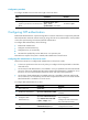
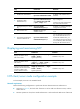
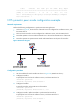
Figure 57 Network diagram
Configuration procedure
1. Set the IP address for each interface as shown in Figure 57. (Details not shown.)
2. Configure Device A:
# Specify the local clock as the reference source, with the stratum level 2.
<DeviceA> system-view
[DeviceA] ntp-service refclock-master 2
3. Configure Device B:
# Display the NTP status of Device B before clock synchronization.
<DeviceB> display ntp-service status
Clock status: unsynchronized
Clock stratum: 16
Reference clock ID: none
Nominal frequency: 64.0000 Hz
Actual frequency: 64.0000 Hz
Clock precision: 2^7
Clock offset: 0.0000 ms
Root delay: 0.00 ms
Root dispersion: 0.00 ms
Peer dispersion: 0.00 ms
Reference time: 00:00:00.000 UTC Jan 1 1900 (00000000.00000000)
# Specify Device A as the NTP server of Device B so that Device B synchronizes to Device A.
<DeviceB> system-view
[DeviceB] ntp-service unicast-server 1.0.1.11
# Display the NTP status of Device B after clock synchronization.
[DeviceB] display ntp-service status
Clock status: synchronized
Clock stratum: 3
Reference clock ID: 1.0.1.11
Nominal frequency: 64.0000 Hz
Actual frequency: 64.0000 Hz
Clock precision: 2^7
Clock offset: 0.0000 ms
Root delay: 31.00 ms
Root dispersion: 1.05 ms
Peer dispersion: 7.81 ms
Reference time: 14:53:27.371 UTC Sep 19 2005 (C6D94F67.5EF9DB22)
The output shows that Device B has synchronized to Device A. The stratum level of Device B is 3,
and that of Device A is 2.
# Display NTP session information for Device B, which shows that an association has been set up
between Device B and Device A.
[DeviceB] display ntp-service sessions