
HP VPN Firewall Appliances System Management and Maintenance Configuration Guide

138
Reference time: 14:53:27.371 UTC Sep 19 2005 (C6D94F67.5EF9DB22)
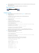
The output shows that Device B has synchronized to Device A. The stratum level of Device B is 3,
and that of Device A is 2.
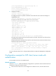
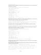
# Display NTP session information for Device B, which shows that an association has been set up
between Device B and Device A.
[DeviceB] display ntp-service sessions
source reference stra reach poll now offset delay disper
**************************************************************************
[12345] 1.0.1.11 127.127.1.0 2 63 64 3 -75.5 31.0 16.5
note: 1 source(master),2 source(peer),3 selected,4 candidate,5 configured
Total associations : 1
Configuration example for NTP broadcast mode with
authentication
Network requirements
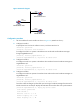
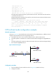
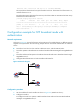
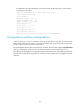
As shown in Figure 62, Firewall C functions as the NTP server for multiple devices on different network
segments and synchronizes the time among multiple devices. Firewall B authenticates the reference
source.
• Firewall C's local clock is to be used as a reference source, with the stratum level 3.
• Firewall C operates in broadcast server mode and sends broadcast messages from GigabitEthernet
0/1.
• Firewall A and Firewall B operate in broadcast client mode and receive broadcast client through
GigabitEthernet 0/1.
• Configure NTP authentication on both Firewall B and Firewall C.
Figure 62 Network diagram
Configuration procedure
1. Set the IP address for each interface as shown in Figure 62. (Details not shown.)
2. Configure Firewall A:
# Configure Firewall A to operate in NTP broadcast client mode and receive NTP broadcast
messages on GigabitEthernet 0/1.