
HP VPN Firewall Appliances VPN Configuration Guide


100
[FirewallA-Tunnel1] source 2002::11:1
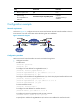
# Specify the IP address of GigabitEthernet 0/2 on Firewall B as the destination address for
interface Tunnel 1.
[FirewallA-Tunnel1] destination 2002::22:1
[FirewallA-Tunnel1] quit
# Configure a static route destined for the IPv6 network Group 2 through interface Tunnel 1.
[FirewallA] ipv6 route-static 2002:3:: 64 tunnel 1
• Configure Firewall B:
# Enable IPv6.
<FirewallB> system-view
[FirewallB] ipv6
# Configure an IPv6 address for GigabitEthernet 0/1.
[FirewallB] interface gigabitethernet 0/1
[FirewallB-GigabitEthernet0/1] ipv6 address 2002:3::1 64
[FirewallB-GigabitEthernet0/1] quit
# Configure an IPv6 address for GigabitEthernet 0/2, which is the physical interface of the tunnel.
[FirewallB] interface gigabitethernet 0/2
[FirewallB-GigabitEthernet0/2] ipv6 address 2002::22:1 64
[FirewallB-GigabitEthernet0/2] quit
# Create interface Tunnel 2.
[FirewallB] interface tunnel 2
# Configure an IPv6 address for interface Tunnel 2.
[FirewallB-Tunnel2] ipv6 address 3001::1:2 64
# Configure the tunnel encapsulation mode as IPv6 over IPv6.
[FirewallB-Tunnel2] tunnel-protocol ipv6-ipv6
# Specify the IP address of GigabitEthernet 0/2 as the source address for interface Tunnel 2.
[FirewallB-Tunnel2] source 2002::22:1
# Specify the IP address of GigabitEthernet 0/2 on Firewall A as the destination address for
interface Tunnel 2.
[FirewallB-Tunnel2] destination 2002::11:1
[FirewallB-Tunnel2] quit
# Configure a static route destined for the IPv6 network Group 1 through interface Tunnel 2.
[FirewallB] ipv6 route-static 2002:1:: 64 tunnel 2
Verifying the configuration
# Display the status of the tunnel interfaces on Firewall A and Firewall B.
[FirewallA] display ipv6 interface tunnel 1
Tunnel1 current state :UP
Line protocol current state :UP
IPv6 is enabled, link-local address is FE80::2013:1
Global unicast address(es):
3001::1:1, subnet is 3001::/64
Joined group address(es):
FF02::1:FF13:1
FF02::1:FF01:1
FF02::1:FF00:0