
HP VPN Firewall Appliances VPN Configuration Guide


118
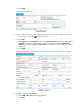
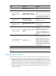
c. Enter 10.1.2.0 as the destination IP address, select 255.255.255.0 from the mask list, and
enter 2.2.2.2 as the next hop.
d. Click Apply.
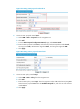
Figure 91 Configuring a static route to Host B
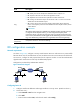
Configuring Device B
1. Configure interface IP addresses and assign interfaces to security zones. (Details not shown.)
2. Create ACL 3101.
a. Select Firewall > ACL from the navigation tree.
b. Click Add.
c. Enter the ACL number 3101, and select the match order Config.
d. Click Apply.
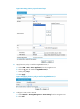
3. Create a rule for ACL 3101 to allow packets from subnet 10.1.2.0/24 to subnet 10.1.1.0/24:
a. From the ACL list, click the icon for ACL 3101.
b. Click Add.
c. Select Permit from the Operation list. Select the Source IP Address box and enter 10.1.2.0 and
0.0.0.255 as the source subnet address and mask, respectively. Select the Destination IP
Address box and enter 10.1.1.0 and 0.0.0.255 as the destination subnet address and mask,
respectively.
d. Click Apply.
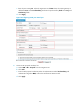
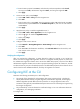
4. Configure an IKE peer named peer:
a. Select VPN > IKE > Peer from the navigation tree.
b. Click Add.
c. Enter the peer name peer. Select the negotiation mode Main. Enter the remote gateway IP
address 1.1.1.1. Select Pre-Shared Key and enter the pre-shared key abcde in the Key and
Confirm Key fi
elds.
d. Clic
k Apply.
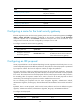
5. Create an IPsec proposal named tran1:
a. Select VPN > IPSec > Proposal from the navigation tree.
b. Click Add.
c. From the IPSec Proposal Configuration Wizard page, select Custom mode.