
HP VPN Firewall Appliances VPN Configuration Guide

8
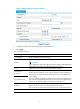
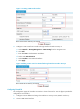
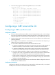
Figure 11 Creating a GRE tunnel interface
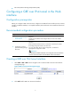
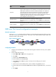
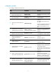
3. Configure a static route from Firewall A through interface Tunnel0 to Group 2:
a. Select Network > Routing Management > Static Routing from the navigation tree.
b. Click Add.
c. Enter 10.1.3.0 as the destination IP address.
d. Select mask 255.255.255.0.
e. Select Tunnel0 as the outbound interface.
f. Click Apply.
Figure 12 Adding a static route from Firewall A through interface Tunnel0 to Group 2
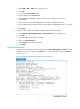
Configuring Firewall B
The configuration pages of Firewall B are similar to those of Firewall A. See the figures provided for
configurations on Firewall A.
1. Configure an IPv4 address and assign the interfaces to security zones. (Details not shown.)
2. Create a GRE tunnel interface: