
HP VPN Firewall Appliances VPN Configuration Guide

9
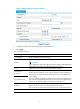
a. Select VPN > GRE > GRE from the navigation tree.
b. Click Add.
c. Enter 0 in the Tunnel Interface field.
d. Enter IP address/mask 10.1.2.2/24.
e. Select Trust from the Zone list. (Select a security zone according to your network
configuration.)
f. Enter the source end IP address 2.2.2.2, the IP address of GigabitEthernet 0/1.
g. Enter the destination end IP address 1.1.1.1, the IP address of GigabitEthernet 0/1 on Firewall
A.
h. Click Apply.
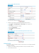
3. Configure a static route from Firewall B through interface Tunnel0 to Group 1:
a. Select Network > Routing Management > Static Routing from the navigation tree.
b. Click Add.
c. Enter 10.1.1.0 as the destination IP address.
d. Select mask 255.255.255.0.
e. Select Tunnel0 as the outbound interface.
f. Click Apply.
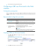
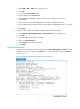
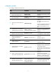
Verifying the configuration
1. Log in to the Web interface of Firewall A and then select Device Management > Interface from the
navigation tree. Click the name link of Tunnel0. You can view the status of interface Tunnel0, as
shown in Figure 13.
Figure 13 Status information and stat
istics of interface Tunnel0