
HP VPN Firewall Appliances VPN Configuration Guide
10
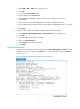
2. From Firewall B, ping the IP address of GigabitEthernet 0/2 on Firewall A.
<FirewallB> ping 10.1.1.1
PING 10.1.1.1: 56 data bytes, press CTRL_C to break
Reply from 10.1.1.1: bytes=56 Sequence=1 ttl=255 time=2 ms
Reply from 10.1.1.1: bytes=56 Sequence=2 ttl=255 time=2 ms
Reply from 10.1.1.1: bytes=56 Sequence=3 ttl=255 time=2 ms
Reply from 10.1.1.1: bytes=56 Sequence=4 ttl=255 time=2 ms
Reply from 10.1.1.1: bytes=56 Sequence=5 ttl=255 time=2 ms
--- 10.1.1.1 ping statistics ---
5 packet(s) transmitted
5 packet(s) received
0.00% packet loss
round-trip min/avg/max = 1/1/2 ms
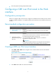
Configuring a GRE tunnel at the CLI
Configuring a GRE over IPv4 tunnel
Configuration guidelines
• The source address and destination address of a tunnel uniquely identify a path. You must configure
the tunnel source address and destination address at both ends of a tunnel and the tunnel source or
destination address at one end must be the tunnel destination or source address at the other end.
• Tunnel interfaces using the same encapsulation protocol must have different source addresses and
destination addresses.
• If you configure a source interface for a tunnel interface, the tunnel interface takes the primary IP
address of the source interface as its source address.
• You can enable or disable the checksum function at both ends of a tunnel.
{ If checksum is enabled at the local end but not at the remote end, the local end calculates the
checksum of a packet to be sent but does not check the checksum of a received packet.
{ If checksum is enabled at the remote end but not at the local end, the local end checks the
checksum of a received packet but does not calculate the checksum of a packet to be sent.
• You can use the following methods to configure a route to a destination over the GRE tunnel:
{ Configure a static route, using the destination address of the original packet as the destination
address of the route and the address of the peer tunnel interface as the next hop.
{ Enable a dynamic routing protocol on both the tunnel interface and the interface connecting the
private network, so the dynamic routing protocol can establish a routing entry with the tunnel
interface as the outgoing interface.
• The IP address of the tunnel interface and the tunnel destination address configured on the tunnel
interface must be in different subnets.
Configuration prerequisites
Configure an IP address for the interface (such as a VLAN interface, an Ethernet interface, or a Loopback
interface) to be used as the source interface of the tunnel interface.