
HP VPN Firewall Appliances VPN Configuration Guide


198
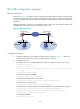
• On Firewall A and Firewall B, add the uplink interface to VRRP group 2 and the downlink interface
to VRRP group 1, and assign the virtual IP address 192.168.0.1/24 to VRRP group 2 and the virtual
IP address 10.1.1.1/2 to VRRP group 1.
• Use Firewall A as the master device to establish an IPsec tunnel with Firewall C and make sure that
Firewall B takes over when Firewall A fails.
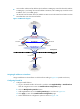
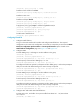
Figure 132 Network diagram
Assigning IP addresses to interfaces
Assign IP addresses to the interfaces on the firewalls according to Figure 132. (Details not shown.)
Configuring Firewall A
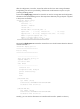
1. Configure stateful failover:
a. Log in to the Web interface of Firewall A, and then select High Reliability > Stateful Failover
from the navigation tree to enter the Stateful Failover Configuration page.
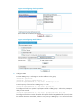
b. Click the Modify Backup Interface button.
c. Add GigabitEthernet 0/3 to the Backup Interface(s) list, as shown in Figure 133.
d. Cli
ck Apply to return to the Stateful Failover Configuration page.
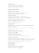
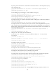
e. Select stateful failover configu
ration options as shown in Figure 134.
Firewall A
Backup link
Host B
IP:10.2.2.2/24
Gateway:10.2.2.1
Firewall B
GE0/3
GE0/3
Host A
IP:10.1.1.2/24
Gateway:10.1.1.1
Branch
Headquarters
Virtual IP address 1:
10.1.1.1/24
Virtual IP address 2:
192.168.0.1/24
GE0/2
192.168.0.5/24
GE0/1
10.1.1.10/24
GE0/2
192.168.0.6/24
GE0/1
10.1.1.20/24
Firewall C
GE0/1
192.168.0.2./24
GE0/2
10.2.2.1/24