
HP VPN Firewall Appliances VPN Configuration Guide

14
For more information about commands interface tunnel, tunnel-protocol, source, destination,
encapsulation-limit and tunnel discard ipv4-compatible-packet, see VPN Command Reference.
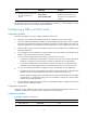
Displaying GRE
Task Command
Remarks
Display information about a
specific or all tunnel interfaces.
display interface [ tunnel ] [ brief [ down ] ] [ |
{ begin | exclude | include }
regular-expression ]
display interface tunnel number [ brief ] [ |
{ begin | exclude | include }
regular-expression ]
Available in any view.
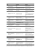
Display IPv6 information about a
tunnel interface.
display ipv6 interface tunnel [ number ]
[ brief ] [ | { begin | exclude | include }
regular-expression ]
Available in any view.
For more information about commands display interface tunnel and display ipv6 interface tunnel, see
VPN Command Reference.
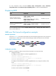
GRE over IPv4 tunnel configuration example
Network requirements
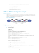
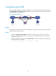
As shown in Figure 14, Firewall A and Firewall B are interconnected through the Internet. Two private IPv4
subnets Group 1 and Group 2 are interconnected through a GRE tunnel between the two firewalls.
Figure 14 Network diagram
Configuration procedure
Before the configuration, make sure Firewall A and Firewall B can reach each other.
1. Configure Firewall A:
# Configure an IPv4 address for interface GigabitEthernet 0/1.
<FirewallA> system-view
[FirewallA] interface gigabitethernet 0/1
[FirewallA-GigabitEthernet0/1] ip address 10.1.1.1 255.255.255.0
[FirewallA-GigabitEthernet0/1] quit
# Configure an IPv4 address for interface GigabitEthernet 0/2, the physical interface of the
tunnel.
[FirewallA] interface gigabitethernet 0/2
[FirewallA-GigabitEthernet0/2] ip address 1.1.1.1 255.255.255.0
[FirewallA-GigabitEthernet0/2] quit
# Create a tunnel interface named Tunnel0.