
HP VPN Firewall Appliances VPN Configuration Guide

250
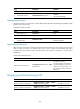
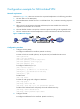
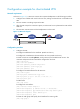
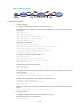
Figure 172 Network diagram
Configuration procedure
1. Configure the LNS:
# Configure IP addresses for interfaces. (Details not shown.)
# Create a local user, configure a username and password for the user, and specify the service
type as PPP.
<LNS> system-view
[LNS] local-user vpdnuser
[LNS-luser-vpdnuser] password simple Hello
[LNS-luser-vpdnuser] service-type ppp
[LNS-luser-vpdnuser] quit
# Configure a VT interface.
[LNS] interface virtual-template 1
[LNS-virtual-template1] ip address 192.168.0.20 255.255.255.0
[LNS-virtual-template1] remote address pool 1
[LNS-virtual-template1] ppp authentication-mode pap
[LNS-virtual-template1] quit
# Configure local authentication for VPN users.
[LNS] domain system
[LNS-isp-system] authentication ppp local
[LNS-isp-system] ip pool 1 192.168.0.2 192.168.0.100
[LNS-isp-system] quit
# Enable L2TP and create an L2TP group.
[LNS] l2tp enable
[LNS] l2tp-group 1
# Configure the local tunnel name and specify the VT interface for receiving packets and the tunnel
name on the LAC.
[LNS-l2tp1] tunnel name LNS
[LNS-l2tp1] allow l2tp virtual-template 1 remote LAC
# Enable tunnel authentication and configure the authentication key.
[LNS-l2tp1] tunnel authentication
[LNS-l2tp1] tunnel password simple aabbcc
[LNS-l2tp1] quit
# Configure a static route so that packets destined for the VPN will be forwarded through the L2TP
tunnel.
[LNS] ip route-static 10.2.0.0 16 virtual-template 1
2. Configure the LAC:
# Configure IP addresses for the interfaces. (Details not shown.)
# Enable L2TP and create an L2TP group.
<LAC> system-view