
HP VPN Firewall Appliances VPN Configuration Guide

25
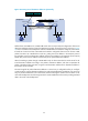
Configuring a P2MP GRE tunnel in the Web
interface
Configuration prerequisites
Before configuring a P2MP GRE tunnel, configure an IP address for the interface (such as a VLAN
interface, an Ethernet interface, or a Loopback interface) to be used as the source interface of the tunnel
interface.
Recommended configuration procedure
Task Remarks
1. Configuring a P2MP GRE tunnel
interface.
Required.
Create a P2MP GRE tunnel interface and configure the related
parameters.
2. Configure a route for packet
forwarding through the tunnel.
Required.
Each end of the tunnel must have a route (static or dynamic) for packet
forwarding through the tunnel to the other end, so that GRE
encapsulated packets can be forwarded correctly.
When you configure a route through the tunnel, you can configure a
static route, using the address of the network segment that the original
packet is destined for as its destination address and the address of the
peer tunnel interface as its next hop. Or, you can enable a dynamic
routing protocol on both the tunnel interface and the interface
connecting the private network, so that the dynamic routing protocol
can establish a routing entry that instructs the device to forward
packets through the tunnel.
For more information about routing configuration, see Network
Management Configuration Guide.
IMPORTANT:
It is not allowed to set up a static route whose destination address is in
the subnet of the tunnel interface.
3. Displaying information about
established P2MP GRE tunnels.
Optional.
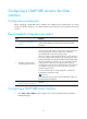
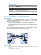
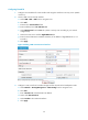
Configuring a P2MP GRE tunnel interface
1. Select VPN > GRE > P2MP from the navigation tree to enter the P2MP GRE tunnel interface
management page.