
HP VPN Firewall Appliances VPN Configuration Guide


28
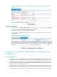
Table 3 Field description
Field Descri
p
tion
Tunnel Interface Name of the tunnel interface.
Tunnel Dest Address IP address of the tunnel destination.
Branch Network
Address/Mask
IP address and mask of the branch network.
GRE Key
GRE key of the tunnel, used to identify the priority of the tunnel entry. If the
tunnel peer device is not configured with a GRE key, nothing will be displayed
for this field.
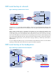
Basic P2MP GRE tunnel configuration example
Network requirements
A company has a network at the headquarters and each of its branches. It is required to implement
communication between the headquarters and the branches through GRE. Figure 24 shows a simplifi
ed
scenario, where there is only one branch.
• Firewall A is the gateway at the headquarters, and Firewall B is the gateway of the branch.
• Host A is an internal user at the headquarters and Host B is an internal user at the branch. A GRE
tunnel is established between Firewall A and Firewall B to implement communication between Host
A and Host B.
If you use P2P GRE tunnels, the number of GRE tunnels to be configured is the same as that of the
branches. To simplify the configuration at the headquarters, you can create a P2MP GRE tunnel interface
on Firewall A, and configure a GRE over IPv4 tunnel interface on Firewall B.
This example uses Firewall B to illustrate the branch gateway configuration. The configuration on other
branch gateways is similar.
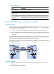
Figure 24 Network diagram
Configuring Firewall A
1. Configure an IPv4 address for each interface and assign the interfaces to security zones. (Details
not shown.)
2. Create a P2MP GRE tunnel interface: