
HP VPN Firewall Appliances VPN Configuration Guide

29
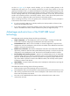
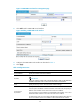
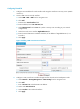
a. Select VPN > GRE > P2MP from the navigation tree.
b. Click Add.
c. Enter 0 in the Tunnel Interface field, and enter IP address/mask 192.168.22.1/24.
d. Select Management from the Zone list. (Select a security zone according to your network
configuration.)
e. Select GigabitEthernet0/1 as the tunnel source interface.
f. Enter 24 as the branch network address mask, and 10 as the tunnel entry aging time.
g. Click Apply.
Figure 25 Adding a P2MP GRE tunnel interface
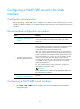
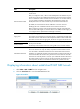
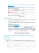
3. Configure a static route from Firewall A through interface Tunnel0 to the branch network:
a. Select Network > Routing Management > Static Routing from the navigation tree.
b. Click Add.
c. Enter 192.168.12.0 as the destination IP address.
d. Select mask 255.255.255.0.
e. Select Tunnel0 as the outbound interface.
f. Click Apply.
Figure 26 Adding a static route from Firewall A through interface Tunnel0 to the branch network