
HP VPN Firewall Appliances VPN Configuration Guide


31
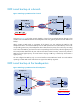
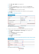
Figure 28 Adding a static route from Firewall B through interface Tunnel0 to the headquarters
node
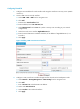
Verifying the configuration
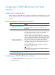
1. On Firewall A, select VPN > GRE > P2MP from the navigation tree, and then click the Tunnel List
tab to view the tunnel entries. There should be no tunnel entry.
2. Ping Host A from Host B. The ping operation succeeds.
3. On Firewall A, click Refresh under the tunnel entry list. The P2MP GRE tunnel entry should have
been installed.
Figure 29 Verifying the configuration result
Configuration example for P2MP GRE tunnel backup at the
headquarters
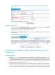
Network requirements
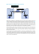
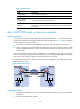
As shown in Figure 54, the headquarters uses two gateways at the egress of the internal network, with
Firewall B for backup. Two GRE tunnels are created on Firewall C, the gateway at the branch, one for
connecting Firewall A and the other for connecting Firewall B. Packets are forwarded along the tunnel
between Firewall A and Firewall C. When a failure occurs along this path, the tunnel between Firewall
B and Firewall C is used to transmit packets.
To meet the previous requirements, you need to establish a P2MP GRE tunnel with the branch on both
Firewall A and Firewall B, establish a GRE over IPv4 tunnel between Firewall A and Firewall B, and on
Firewall A, configure the tunnel interface of the GRE over IPv4 tunnel as the backup interface of the P2MP