
HP VPN Firewall Appliances VPN Configuration Guide


32
GRE tunnel interface. Thus, when Firewall A cannot find the corresponding tunnel entry for a packet, it
delivers the packet to Firewall B, which then forwards the packet to Firewall C.
To avoid looping, do not configure the tunnel interface of the GRE over IPv4 tunnel as the backup
interface of the P2MP GRE tunnel interface on Firewall B.
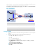
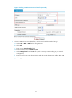
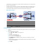
Figure 30 Network diagram
Device Interface IP address
Device
Interface
IP address
Firewall A GE0/1 11.1.1.1/24 Firewall B GE0/1 11.1.1.2/24
GE0/2 10.1.1.1
/
24
GE0/2
10.1.1.2
/
24
GE0/3 192.168.11.1/24
GE0/3
192.168.11.2
/
24
Tunnel0 172.168.1.1/24 Tunnel0 172.168.2.2/24
Tunnel1 192.168.22.1/24
Tunnel1
192.168.22.2/24
Firewall C GE0/1 11.1.1.3
/
24
Firewall C
Tunnel0
172.168.1.3/24
GE0/2 192.168.12.1/24 Tunnel1 172.168.2.3/24
Configuring Firewall A
1. Configure an IPv4 address for each interface and assign the interfaces to security zones. (Details
not shown.)
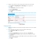
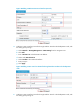
2. Create GRE over IPv4 tunnel interface, with the tunnel interface number being 1:
a. Select VPN > GRE > GRE from the navigation tree.
b. Click Add.
c. Enter 1 in the Tunnel Interface field.
d. Enter IP address/mask 192.168.22.1/24.
e. Select Management from the Zone list. (Select a security zone according to your network
configuration.)
f. Enter the tunnel source IP address 10.1.1.1.
g. Enter the tunnel destination IP address 10.1.1.2.
h. Click Apply.
GE0/2
GE0/1
GE0/1
Firewall A
Firewall B
(Backup gateway)
IPv4 network
Firewall C
GE0/2
GE0/1 GE0/2
Tunnel0
Tunnel0
Tunnel0
Tunnel1
Tunnel1
Tunnel1
Host A
Host B
Host C
GRE P2MP tunnel
GRE over IPv4 tunnel
Headquarters
Branch
GE0/3
GE0/3