
HP VPN Firewall Appliances VPN Configuration Guide


430
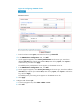
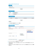
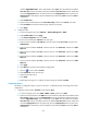
d. Select the IPsec authentication method Pre-Shared Key and then enter abcde in the Key and
Confirm Key fields.
e. Select IP Address as both the remote ID type and the local ID type.
f. Click Apply.
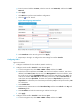
3. Configure OSPF:
a. From the navigation tree, select Network > Routing Management > OSPF.
b. Select Enable OSPF and click Apply.
c. In the Area Configuration area, click Add.
d. Enter the area ID 0. Select Normal as the area type.
e. Enter the network address 192.168.3.0, select the network mask 0.0.0.255, and then click
Add Network.
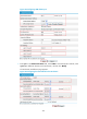
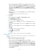
f. Enter the network address 10.0.1.0, select the network mask 0.0.0.255, and then click Add
Network.
g. Enter the network address 10.0.3.0, select the network mask 0.0.0.255, and then click Add
Network.
h. Click Apply.
i. Click More>> to perform OSPF interface configuration.
j. Click the icon of interface Tunnel1.
k. Select Broadcast as the network type.
l. Selec
t 0 as the DR priority.
m. Click Apply.
Configuring Spoke 2
The Spoke 2 configuration page is similar to the Hub 1 configuration page. See the figures for Hub 1
configuration.
1. Configure IP addresses for the interfaces. (Details not shown.)
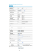
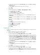
2. Configure tunnel interface Tunnel1 for VPN domain vpn1:
a. From the navigation tree, select VPN > DVPN > Client, and then click Add.
b. Select the tunnel encapsulation mode UDP. Enter the tunnel interface number 1. Enter the IP
address/mask 10.0.1.4/24. Select security zone Management for the tunnel interface. Select
the tunnel source interface GigabitEthernet0/1. Enter the VPN domain name vpn1. Enter the
VAM server address 192.168.1.22. Enter the secondary VAM server address 192.168.1.33.
Enter the VAM client username dvpn1spoke2. Enter the VAM client password dvpn1spoke2.
Enter the password dvpn1spoke2 for confirmation. Enter the VAM client pre-shared key 123.
c. Select Enable IPsec.
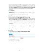
d. Select the IPsec authentication method Pre-Shared Key and then enter abcde in the Key and
Confirm Key fields.
e. Select IP Address as both the remote ID type and the local ID type.
f. Click Apply.
3. Configure tunnel interface Tunnel2 for VPN domain vpn2:
a. From the navigation tree, select VPN > DVPN > Client, and then click Add.
b. Selec
t tunnel encapsulation mode GRE. Enter tunnel interface n
umber 2. Enter IP address/mask
10.0.2.4/24. Select security zone Management for the tunnel interface. Select tunnel source