
HP VPN Firewall Appliances VPN Configuration Guide

434
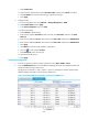
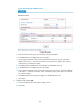
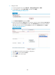
8. Click the DVPN Session tab to view all DVPN session information.
The figure shows that in VPN 1 and VPN 2, Spoke 2 has established two Spoke-Hub permanent
tunnels, one with Hub 1 and the other with Hub 2. The session information on Spoke 1 and Spoke
3 is similar.
Figure 332 Viewing DVPN session information on Spoke 2
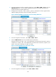
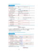
9. From Spoke 2, ping the private address of Spoke 3 10.0.5.1.
The ping operation succeeds.
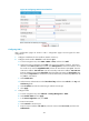
10. Refresh the DVPN session list of Spoke 2.
Figure 333 sh
ows the DVPN s
ession information. The information shows that Spoke 2 and Spoke 3 have
established a dynamic Spoke-Spoke tunnel.
Figure 333 Viewing DVPN session information on Spoke 2
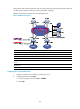
Hub-Spoke DVPN configuration example
Network requirements
In the Hub-Spoke network shown in Figure 348, data is forwarded along Hub-Spoke tunnels. The primary
and secondary VAM servers manage and maintain information about the nodes. The RADIUS server on