
HP VPN Firewall Appliances VPN Configuration Guide


39
This makes the priority of this route lower than that of the static route of interface Tunnel0, making
sure Firewall C prefers the tunnel between Firewall A and Firewall C for packet forwarding.
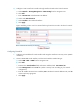
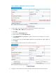
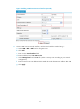
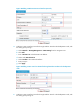
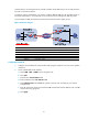
a. On the static route management page, click Add.
b. Enter 192.168.11.0 as the destination IP address.
c. Select mask 255.255.255.0.
d. Select Tunnel1 as the outbound interface.
e. Enter priority 10.
f. Click Apply.
Figure 40 Adding a static route from Firewall C through interface Tunnel1 to the headquarters
node
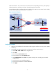
If the link between Firewall A and Firewall C goes down, Firewall C will sense the failure and try to send
packets to Firewall B, initiating the establishment of the tunnel between Firewall B and Firewall C. Only
then can Firewall B learn the tunnel entry.
If Firewall A and Firewall C are directly connected, configuring a static route on Firewall C can make sure
that Firewall C senses the failure of the link between Firewall A and Firewall C. If the two are not directly
connected, you need to use either of the following methods to achieve the effect:
• Configure dynamic routing on Firewall A, Firewall B, and Firewall C.
• On Firewall C, associate the static route with a track entry, so as to use the track entry to track the
status of the static route. For more information about a track entry, see High Availability
Configuration Guide.
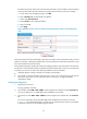
Verifying the configuration
1. Ping Host A from Host C.
The ping operation succeeds.
2. On Firewall B, select VPN > GRE > P2MP from the navigation tree and then click the Tunnel List tab.
You can see that there is no P2MP GRE tunnel established on Firewall B.
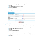
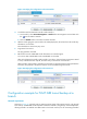
3. On Firewall A, select VPN > GRE > P2MP from the navigation tree and then click the Tunnel List
tab.
You can see information about the P2MP GRE tunnels established on Firewall A, as shown
in Figure 41.
This indicates that there is a tunnel entry to reach the branch network,
and packets
to the branch network are forwarded through Firewall A.