
HP VPN Firewall Appliances VPN Configuration Guide


56
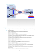
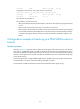
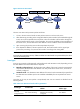
Figure 55 Network diagram
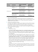
Device Interface IP Address
Device
Interface
IP Address
Firewall A GE0/1 11.1.1.1/24 Firewall B GE0/1 11.1.1.2/24
GE0/2 172.17.17.1/24
GE0/2
192.168.1.2
/
24
Tunnel0 192.168.22.1/24
Tunnel0
192.168.22.2/24
Firewall C GE0/1 11.1.1.3/24 Firewall C Tunnel0 192.168.22.3/24
GE0/2 192.168.1.3
/
24
Configuration procedure
1. Configure IP addresses and masks for interfaces according to Figure 55. (Details not shown.)
2. Configure Firewall A:
# Create a tunnel interface named Tunnel0 and configure an IP address for it.
<FirewallA> system-view
[FirewallA] interface tunnel 0
[FirewallA-Tunnel0] ip address 192.168.22.1 255.255.255.0
# Configure the tunnel encapsulation mode of the tunnel interface Tunnel0 as P2MP GRE.
[FirewallA-Tunnel0] tunnel-protocol gre p2mp
# Configure the mask of the branch network connected to the tunnel interface Tunnel0 as
255.255.255.0.
[FirewallA-Tunnel0] gre p2mp branch-network-mask 255.255.255.0
# Set the tunnel entry aging time to 20 seconds.
[FirewallA-Tunnel0] gre p2mp aging-time 20
# Configure the source IP address of the tunnel interface Tunnel0.
[FirewallA-Tunnel0] source 11.1.1.1
[FirewallA-Tunnel0] quit
# Configure a static route to the branch network with the outgoing interface being the tunnel
interface Tunnel0.
[FirewallA] ip route-static 192.168.1.0 255.255.255.0 tunnel 0
3. Configure Firewall B:
# Create a tunnel interface named Tunnel0 and configure an IP address for it.
<FirewallB> system-view
[FirewallB] interface tunnel 0
[FirewallB-Tunnel0] ip address 192.168.22.2 255.255.255.0
# Configure the tunnel encapsulation mode of the tunnel interface Tunnel0 as GRE over IPv4.