
Installation and Getting Started Guide for 745wl and ACM xl 2006-06


D-1
D
CABLE AND CONNECTOR SPECIFICATIONS
This appendix describes the console port and the standard Ethernet cables to be used. This appendix
contains the following sections:
Serial Console Port . . . . . . . . . . . . . . . . . . . . . . . . . . . . . . . . . . . . . . . . . . . . . . . . . . . . . . . . . . D-1
10/100 Downlink Ethernet Cables . . . . . . . . . . . . . . . . . . . . . . . . . . . . . . . . . . . . . . . . . . . . . D-2
Serial Console Port
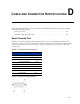
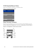
Table D-1 shows the pin assignments for the DB-9 serial console port, and Figure D-1 shows the pin
configuration. The console port is configured as an EIA/TIA-232 data terminal equipment (DTE) adapter.
If you are connecting a console device such as a laptop, you must use a serial crossover cable (null
modem cable).
Figure D-1. Console Port Pin Configuration
Table D-1. Pin Assignments for Console Port
Pin Assignment Symbol
1 Data Carrier Detect DCD
2 Receive Data RXD
3 Transmit Data TXD
4 Data Terminal Ready DTR
5 Signal Ground GND
6 Data Set Ready DSR
7 Request to Send RTS
8 Clear to Send CTS
9 Ring Indicator RI