
Installation and Getting Started Guide for 745wl and ACM xl 2006-06


D-2 ProCurve Secure Access 700wl Series Installation and Getting Started Guide
10/100 Downlink Ethernet Cables
Table D-2 shows the RJ-45 pin assignments for 10/100 Ethernet cables.
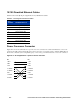
Power Crossover Connector
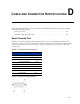
Figure D-2 shows the schematic for a power crossover connector. In normal circumstances a crossover
connector should not be required. However, if for any reason you need to plug a +48VDC (IEEE 802.3af)
device into a -48VDC (Cisco-compatible) port, or vice versa, you will need to use a crossover connector.
Figure D-2. Pin assignment for a power crossover connector.
Table D-2. Pin Assignment for Ethernet Cables
Pin
Number
Standard Ethernet
1 Incoming Data + (RD+)
2 Incoming Data - (RD-)
3 Outgoing Data + (TD+)
4 No Connection (NC)
5 No Connection (NC)
6 Outgoing Data - (TD-)
7 No Connection (NC)
8 No Connection (NC)
Pin Pin
1 RD+ 1 TD+
2 RD- 2 TD-
3 TD+ 3 RD+
4 +48VDC 4 -48VDC
5 +48VDC 5 -48VDC
6TD- 6 RD-
7 -48VDC 7 +48VDC
8 -48vdc 8 +48vdc