HP AllianceONE Extended Services zl Module with Riverbed® Steelhead® RiOS® Application Installation and Getting Started Guide
HP AllianceONE Extended Services zl Module with Riverbed® Steelhead® RiOS® Application October 2010 Installation and Getting Started Guide
© Copyright 2010 Hewlett-Packard Development Company, L.P. The information contained herein is subject to change without notice. All Rights Reserved. This document contains proprietary information, which is protected by copyright. No part of this document may be photocopied, reproduced, or translated into another language without the prior written consent of HewlettPackard.
Contents 1 Overview Accelerating WAN Connections . . . . . . . . . . . . . . . . . . . . . . . . . . . . . . . . . . . 1-1 Discovery of Remote Appliances . . . . . . . . . . . . . . . . . . . . . . . . . . . . . . . . 1-2 Deployment . . . . . . . . . . . . . . . . . . . . . . . . . . . . . . . . . . . . . . . . . . . . . . . . . 1-3 Switch-Based Deployment . . . . . . . . . . . . . . . . . . . . . . . . . . . . . . . . . . 1-3 Example Deployments . . . . . . . . . . . . . . . . . . . . . . . . . . . . . . .
3 Getting Started Initial Configuration . . . . . . . . . . . . . . . . . . . . . . . . . . . . . . . . . . . . . . . . . . . . . 3-1 Ensure the HP zl Switch Recognizes the HP AllianceONE Extended Services zl Module . . . . . . . . . . . . . . . . . . . . . . . . . . . . . . . . . . . 3-1 Internal Ports on the HP AllianceONE Extended Services zl Module . . . . 3-2 Configure Transparent Mode on the HP zl Switch . . . . . . . . . . . . . . . . . . . 3-3 Plan Your Transparent Mode Configuration . . . . . . . .
A EMC Regulatory Statements B Waste Electrical and Electronic Equipment (WEEE) Statements C Hardware Components Front Panel Buttons, LEDs, and Connectors . . . . . . . . . . . . . . . . . . . . . . . . C-1 Upper Deck . . . . . . . . . . . . . . . . . . . . . . . . . . . . . . . . . . . . . . . . . . . . . . . . . . . C-2 Internal Ports . . . . . . . . . . . . . . . . . . . . . . . . . . . . . . . . . . . . . . . . . . . . . . . . . C-3 Serial Numbers . . . . . . . . . . . . . . . . . . . . . . . . . . . . .
vi
1 Overview Accelerating WAN Connections Large enterprises spend a significant portion of their IT budgets on storage and networks, such as redundant servers and storage and the required backup equipment. They then lease WAN lines to connect branch offices to the corporate network so that employees at those branch offices can access data on the corporate network. Unfortunately, WANs often have low throughput and high latency because: ■ WAN lines have limited bandwidth.
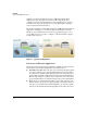
Overview Accelerating WAN Connections As Figure 1-1 shows, the Extended Services zl Module with Steelhead Application is typically deployed at a branch office. This application communicates with a Steelhead appliance that is installed at the corporate main office. The two work together to accelerate WAN traffic exchanged between the branch and main offices. The Steelhead appliance and the Extended Services zl Module with Steelhead application communicate over a private WAN or virtual private network (VPN).
Overview Accelerating WAN Connections Deployment The Riverbed Steelhead appliance and the Extended Services zl Module with Steelhead Application are deployed differently. The Steelhead appliance is deployed inline, while the Extended Services zl Module with Steelhead Application is deployed in an HP 5400zl or 8200zl Switch Series. Inline Deployment In Figure 1-1, the Steelhead appliance at the main office has been deployed inline between a switch and a firewall.
Overview Accelerating WAN Connections packets that match a specific criteria and forwarding the packets to the Steelhead Application, the HP 5400zl or 8200zl switch does not take any further action on the intercepted packets. Transparent Mode is available only when an Extended Services zl Module is installed in an HP 5400zl or 8200zl switch. The switch must also be running software version K.14.58 or above. (See “Update the Switch Software” on page 2-4 in Chapter 2: “Hardware Installation.
Overview Accelerating WAN Connections ■ Zone policy—A zone policy defines which packets are selected, based on the source zone and the destination zone. The source and the destination must be different zones. That is, the HP switch will not intercept packets that are exchanged between switch ports that are assigned to the same zone. The zone policy also specifies the direction of the packets—unidirectional—and the action that should be taken—intercept.
Overview Accelerating WAN Connections In a bridging only configuration, the HP switch: ■ Intercepts the packets that meet the criteria defined in the Transparent Mode configuration on the switch ■ Forwards the intercepted packets to the Steelhead Application This example shows two user-defined zones, the Inside zone and the Outside zone. Notice that all the devices on the network are untagged members of VLAN 1.
Overview Accelerating WAN Connections Figure 1-3. Routing with Multiple VLANs External routing. In this deployment, the HP 5400zl or 8200zl switch has an external firewall that is functioning as a router. For example, the switch might include an HP Threat Management Services zl Module, which is routing traffic and providing firewall services (as well as IPS and VPN services). The Steelhead Application does not receive traffic directly from the outside subnet but only from the TMS zl Module.
Overview Accelerating WAN Connections 1-8
2 Hardware Installation The HP AllianceONE Extended Services zl Module with the Riverbed® Steelhead® RiOS® Application is designed to run in an HP 5400zl or 8200zl Series Switch. Table 2-1 lists the tasks that you will perform to get the HP AllianceONE Extended Services zl Module up and running so that you can begin the initial configuration process (as outlined in Chapter 3: “Getting Started”). If the HP 5400zl or 8200zl switch has already been installed, move to “Update the Switch Software” on page 2-4.
Hardware Installation Module Locator LED HDD and Network activity LEDs Module Shutdown button Management port PCIe slot 1 PCIe slot 2 Module Status LED USB port Figure 2-1. Front panel Operating Systems (OSs) When the Extended Services zl Module ships, it includes the hardware along with: ■ HP Service OS The primary and backup Service OS reside on the Compact Flash (CF).
Hardware Installation When you install the Extended Services zl Module for the first time, it boots directly to the Steelhead Application, where it should remain during both the initial setup and normal operations. Initially, you will need to activate the Steelhead application by obtaining a license from Riverbed and following the process outlined “Activating the Token and Installing the Steelhead Application Licenses” on page 3-19 in Chapter 3: “Getting Started.” Figure 2-2.
Hardware Installation Update the Switch Software Update the Switch Software If you need to install the HP 5400zl or 8200zl switch, refer to the switch’s Installation and Getting Started Guide. (This guide shipped with the switch, and it is also available at www.hp.com/networking/manuals.) Before installing the Extended Services zl Module, you must update the HP 5400zl or 8200zl switch software to version K.14.58 or above. Otherwise the switch will not recognize the module. Note Software versions K.15.
Hardware Installation Update the Switch Software 4. You can copy the software from the USB drive directly to the switch, or you can copy the file to a TFTP server and upload it from there. • USB drive—Follow these steps: i. Insert the USB drive in the HP 5400zl or 8200zl switch’s USB slot. ii. Enter the following command from the HP 5400zl or 8200zl switch CLI: hostswitch# copy usb flash secondary iii. When prompted, press [y]. • TFTP server—Follow these steps: i.
Hardware Installation Update the Switch Software 6. Set the startup-config file for the secondary software: hostswitch# startup-default secondary config For example: hostswitch# startup-default secondary config config1 If you do not know the name of the config file that you are using, you can use the help function to see the names of files on your system: hostswitch# startup-default secondary config ? 7. Reboot the switch to the secondary software: hostswitch# boot system flash secondary 8.
Hardware Installation Set the Switch Time Set the Switch Time To follow best practices, you should ensure that the HP 5400zl or 8200zl switch is using the correct time. This helps ensure that switch operations can be performed without error, particularly when the switch is interacting with other applications and network infrastructure devices. Setting the correct time also ensures that event logs have the correct time, allowing you to monitor or troubleshoot problems more easily.
Hardware Installation Set the Switch Time 6. If you plan to activate Daylight Saving Time on the Steelhead application, you must activate it on the HP switch: Syntax: time daylight-time-rule < none | alaska | continental-us-and-canada | middle-europe-and-portugal | southern-hemisphere | western-europe |user-defined> Select the region that applies to you. 7. Check the switch time and verify that it is correct: hostswitch(config)# clock 8.
Hardware Installation Set the Switch Time 5. If you plan to activate Daylight Saving Time on the Steelhead application, you must activate it on the HP switch: Syntax: time daylight-time-rule < none | alaska | continental-us-and-canada | middle-europe-and-portugal | southern-hemisphere | western-europe | user-defined> Select the region that applies to you. 6.
Hardware Installation Install the Extended Services zl Module Install the Extended Services zl Module Installation Precautions ■ Static electricity can severely damage the electronic components on the module. When handling and installing the module, follow these procedures to avoid damage from static electricity: • Handle the module by its bulkhead or edges and avoid touching the components and the circuitry on the board.
Hardware Installation Install the Extended Services zl Module Installation Steps 1. Use a Torx T-10 or flat-bladed screwdriver to unscrew the screws in the cover plates over slots A and C, where you will install the Extended Services zl Module. Note that the module occupies two slots. Remove the cover plates from both slots and store them for possible future use. 2. Hold the module by its bulkhead, taking care not to touch the metal connectors or components on the board. 3. Open the extractor handles.
Hardware Installation Install the Extended Services zl Module The procedure to replace or remove a module is described on page C-6 in the Web version of this document at www.hp.com/networking/manuals. Appendix C also describes the procedure to replace the module’s Hard Disk Drive (HDD) and the Compact Flash (CF) card. Verify that the Module Is Installed Correctly After you install the Extended Services zl Module, it undergoes an installation and configuration process that may take several minutes.
Hardware Installation Environmental Specifications Environmental Specifications Table 2-3 lists the maximum temperatures and other environmental specifications for Extended Services zl Modules. Table 2-3. Environmental Specifications Temperature Operating Non-Operating 0C to 45C (32F to 113F)1 -10C to 65C (-10F to 149F) Relative humidity (non-condensing) 15% to 90% at 40C (104F) 15% to 90% at 65C (149F) Maximum altitude 3.0 km (10,000 ft) 4.6 km (15,000 ft) 1.
Hardware Installation Environmental Specifications 2-14
3 Getting Started Initial Configuration At this point, the HP AllianceONE Extended Services zl Module with the Riverbed® Steelhead® RiOS® Application should be installed in the HP 5400zl or 8200zl Series switch.
Getting Started Initial Configuration You will see output similar to the following: Status and Counters – Module Information Chassis: 5406zl J8697A Serial Number: SG841SU0RI Management Module: J8726A Serial Number: YYYYYYYYY Slot Module Description Serial Number ---- --------------------------------------A C D >Module C Extension Slot ProCurve J9567A ONE Ext Svs zl Module SG9604Q083 ProCurve J9308A Gig-T/SFP PoE+ zl Module Notice that the output shows the Extended Services zl Module in slot C.
Getting Started Initial Configuration Port 2 (2) is sometimes referred to as the normal port because it functions as a normal traffic port. In addition, management traffic and communications between the Extended Services zl Module and the HP zl switch are sent on this port. By default, both internal ports are untagged members of the default VLAN on the HP zl switch. (The default VLAN is typically VLAN 1.
Getting Started Initial Configuration Zone. A zone is a logical group of switch ports. For example, you might create an internal zone and assign all the ports on the internal network to this zone. You might then create an external zone and assign the firewall’s switch port to this zone. Zone Policy.
Getting Started Initial Configuration 2. Enter the class command from the global configuration context. Syntax: [no] class zone Defines a zone class, where < zone name > is a text string (64 characters maximum). After you enter the class command, you enter the class configuration context to configure match criteria. A traffic class contains a series of match and ignore commands, which specify the criteria used to classify packets.
Getting Started Initial Configuration 2. Add ports D1-D23 to the internal zone. The clients and servers attached to these ports are part of the example internal network. hostswitch(config-class)# port-list d1-d23 3. Enter the exit command to exit the class configuration context. hostswitch(config-class)# exit hostswitch(config)# 4. Create the RouterZone, which will contain the port that connects to the external router. hostswitch(config)# class zone RouterZone 5.
Getting Started Initial Configuration View Zones After you configure the zones, you can view your configuration: hostswitch# show class For the example network, you would see the following output: class zone “BYPASS” exit class zone “RouterZone” port-list D24 exit class zone “SWITCH_SELF” exit class zone “InternalZone” port-list D1-D23 exit class zone “SteelheadZone” port-list C2 exit Notice that the output contains the two zones that are created automatically: BYPASS and SWITCH_SELF.
Getting Started Initial Configuration 2. Add ports to the zone. hostswitch(config-class)# port-list For , specify the port or ports you want to add to the zone. If one of the ports was previously assigned to another zone, it will be reassigned to this zone. If you try to edit a policy that has already been associated with the Steelhead Application, the editing changes are not accepted, and an error message is displayed. 3.
Getting Started Initial Configuration 2. To configure the switch to intercept the traffic sent to ports that are associated with a zone, enter one or more class action commands from the policy configuration context. Syntax: [no] [seq-number] class zone < source zone name > < destination zone name > action intercept unidirectional Defines the source and destination zone classes for packets that must be captured and forwarded to the Steelhead application.
Getting Started Initial Configuration 3.
Getting Started Initial Configuration To view the example zone policy created in the previous section, you would enter: hostswitch# show policy Steelhead-Interception-Rules Statements for Policy "Steelhead-Interception-Rules" 1 class zone "InternalZone" "RouterZone" action intercept unidirectional 2 class zone "RouterZone" "InternalZone" action intercept unidirectional 3 class zone "SteelheadZone" "RouterZone" action intercept unidirectional 4 class zone "RouterZone" "SteelheadZone" action intercept unidir
Getting Started Initial Configuration b. Enter the “no” form of the class zone command: hostswitch(config-policy)# no class zone action intercept unidirectional 3. Exit the policy configuration context: hostswitch(config-policy)# exit 4.
Getting Started Initial Configuration The following output reflects the example configuration explained in previous sections. Notice that the output indicates “no zone policy is serviced” by this Steelhead application.
Getting Started Configure the Steelhead Application Configure the Steelhead Application After you configure zones and zone policies for your environment, you can begin configuring the Steelhead Application. Complete the Initial Setup on the Steelhead Application You will access the application through the HP zl switch CLI. 1. Enter: hostswitch(config)# service tech Remember that you can use the show modules command to view the slot in which the Extended Services zl Module is installed. 2.
Getting Started Configure the Steelhead Application 7. Answer yes if you want to have your network DHCP server assign the Steelhead application a dynamic IP address. Answer no if you want to assign it a static IP address. If you answer no, you will be prompted to enter the static IP address, network mask, default gateway, DNS server, and domain name. Refer to Table 3-1 to complete the initial configuration wizard. If you answer yes, the next prompt is displayed. Step 3: Admin password? 8.
Getting Started Configure the Steelhead Application The next prompt is displayed: Step 9: Would you like to activate the out-of-path configuration? [no] 14. Answer no. The wizard will allow you to confirm the settings you have selected. It displays information similar to the following: You have entered the following information: 1. Hostname: amnesiac 2. Use DHCP on primary interface: yes 3. Admin password: ****** 4. SMTP server: exchange 5. Notification email address: 6.
Getting Started Configure the Steelhead Application Table 3-1. Steelhead Configuration Wizard Wizard Prompt Description Example Step 1: Host name? Enter the host name for the Steelhead Application. Step 1: hostname? amnesiac Step 2: Use DHCP on the primary interface? You can enable DHCP to automatically assign an IP address to the primary interface for the Steelhead Application. Riverbed recommends that you do not use DHCP. The default value is no.
Getting Started Configure the Steelhead Application Wizard Prompt Description Example Step 12: Set the primary interface duplex? Enter the duplex mode on the primary Step 12: Set the primary interface interface. Make sure this value matches duplex? [auto] auto the settings on your router or switch. The default value is auto. Step 13: Would you like to activate Enter no at the system prompt to the in-path configuration? configure in-path support.
Getting Started Configure the Steelhead Application Activating the Token and Installing the Steelhead Application Licenses To activate the Steelhead Application, you need the token that is located on the HP License Registration Card, which shipped with the HP AllianceONE Extended Services zl Module. You will use this token to generate a license request key and the Steelhead Application licenses. You can generate a license request key using the Steelhead CLI or the Steelhead Web browser interface.
Getting Started Configure the Steelhead Application 4. Move to the enable mode and then to the configuration mode in the Steelhead Application CLI. amnesiac > enable amnesiac # config terminal amnesiac (config) # 5. Enter the license request set-token command to activate the token: amnesiac (config) # license request set-token This token is located on the HP License Registration card, which shipped with the Extended Services zl Module with Steelhead Application. 6.
Getting Started Configure the Steelhead Application • If you are not a registered user of Riverbed products, go to the Riverbed Licensing Portal at https://licensing.riverbed.com (which is a public Web site). Click Activate License. On the Activate Licenses page, enter your license request key and click Submit. Then enter your company information to complete your request. Figure 3-2. Riverbed Licensing Portal 8.
Getting Started Configure the Steelhead Application amnesiac (config) # install license XXX-SH10EXCHYYYYZZZZ-1-XXXX-YYYY-ZZZZ You must restart the optimization service for your changes to take effect. amnesiac (config) # install license XXXSH10MSPEC1050_ZM-YYYY-ZZZZ-1-XXXX-YYYY-ZZZZ You must restart the optimization service for your changes to take effect.
Getting Started Configure the Steelhead Application To enter the token key and install a license using the Steelhead management console, complete the following steps. Note To connect to the management console, you must know the IP address or the host and domain that you assigned in the configuration wizard. You must also know the administrator password, and cookies and JavaScript must be enabled in your Web browser. 1. Enter the URL for the management console in your Web browser: [http | https]://
Getting Started Configure the Steelhead Application Figure 3-4. Configure > Maintenance > Licenses Page 2. Under License Request Key, type the token and click Generate License Request Key. This token is located on the HP License Registration card, which shipped in the box with the Extended Services zl Module with Riverbed Application. Note If you did not receive the HP License Registration Card, contact HP Support.
Getting Started Configure the Steelhead Application ■ If you are a registered user of Riverbed products, go to the Riverbed Technical Support Web site at https://support.riverbed.com/account/ tokens/ to generate your license keys. Log in using your account credentials and click Accounts > Tokens. Under License Request Keys, enter your license request key and click Redeem. Figure 3-5.
Getting Started Configure the Steelhead Application After your licenses are generated, they are displayed online and are then emailed to you for reference. 4. Return to the Configure > Maintenance > Licenses page and click Add a New License. 5. Copy and paste the license key into the text box. Separate multiple license keys with a space, Tab, or Enter. 6. Click Add. 7. Click Save to save your settings permanently. 8.
Getting Started Configure the Steelhead Application Serial: Model: Revision: Version: XXXYYYXXXYYYXXXYY 1050 (1050_ZM) A 6.1.0 Associate the Zones and Zone Policies with the Steelhead Application You can now associate the zones and zone polices that you created on the HP zl switch with the Steelhead Application. Follow these steps. 1. View the zones: amnesiac (config)# show in-path procurve zones id 0 1 2 3 4 5 6 7 8 9 2.
Getting Started Configure the Steelhead Application The wan0_0 interface is the external router. In the example configuration, you would map this interface to the RouterZone, which has the zone ID1. amnesiac (config)# in-path procurve map zone id 1 interface wan0_0 Note Do not assign an interface to the SWITCH_SELF or BYPASS zones. 3. Enable the zone policy. a. Name the zone policy.
Getting Started Configure the Steelhead Application 8. Check your configuration settings: amnesiac (config)# show in-path Enabled: yes Kickoff: no Maintain Multipath: no Main Interface: inpath0_0 Asymmetric Routing Detection: yes Asymmetric Routing Pass Through: yes Optimizations Enabled On: inpath0_0 VLAN Tag IDs: inpath0_0: 1 9. View additional information with the show procurve all command.
Getting Started Configure the Steelhead Application 11. Press Ctrl-Z to return the HP zl switch CLI. 12. Verify that the Steelhead Application has added a zone policy to the HP zl switch’s running-config.
Getting Started Configure the Steelhead Application Connection Status: OK Policy Used: Steelhead-Inception-Rules Policy Status: Active Policy Expires: Never Bind Port: C1 (Link Up) Normal Port: C2 (Link Up) Fail Action Type: Bypass Fail Status: No failure Times Fail-Action applied: 0 Application-Health Heartbeat Configuration: Application Name: STEELHEAD Application Instance: STEELHEAD-C Status: Active Stats: Heartbeats received: 344752 Failures: 0 Policy Used: Steelhead-Inception-Rules Policy Status: Acti
Getting Started Configure the Steelhead Application Access the Steelhead Management Console You can use the Steelhead Application management console to: ■ Check and modify your configuration settings ■ Manage the application ■ View performance reports and system logs You can connect to the Steelhead Management Console through any supported Web browser. Cookies and Javascript must be enabled in your Web browser. To access the management console, complete these steps. 1.
EMC Regulatory Statements A EMC Regulatory Statements U.S.A. - FCC Class A This equipment has been tested and found to comply with the limits for a Class A digital device, pursuant to Part 15 of the FCC Rules. These limits are designed to provide reasonable protection against interference when the equipment is used in a commercial environment.
EMC Regulatory Statements Japan - VCCI Class A Korea Taiwan European Community Declaration of Conformity This product is designed for operation with HP switches that have zl module slots. Refer to the Declarations of Conformity included in the Installation Guides for those products.
Waste Electrical and Electronic Equipment (WEEE) Statements B Waste Electrical and Electronic Equipment (WEEE) Statements Disposal of Waste Equipment by Users in Private Household in the European Union This symbol on the product or on its packaging indicates that this product must not be disposed of with your other household waste.
Waste Electrical and Electronic Equipment (WEEE) Statements Laitteiden hävittäminen kotitalouksissa Euroopan unionin alueella Jos tuotteessa tai sen pakkauksessa on tämä merkki, tuotetta ei saa hävittää kotitalousjätteiden mukana. Tällöin hävitettävä laite on toimitettava sähkölaitteiden ja elektronisten laitteiden kierrätyspisteeseen.
Waste Electrical and Electronic Equipment (WEEE) Statements Smaltimento delle apparecchiature da parte di privati nel territorio dell'Unione Europea Questo simbolo presente sul prodotto o sulla sua confezione indica che il prodotto non può essere smaltito insieme ai rifiuti domestici. È responsabilità dell'utente smaltire le apparecchiature consegnandole presso un punto di raccolta designato al riciclo e allo smaltimento di apparecchiature elettriche ed elettroniche.
Waste Electrical and Electronic Equipment (WEEE) Statements Descarte de Lixo Elétrico na Comunidade Européia Este símbolo encontrado no produto ou na embalagem indica que o produto não deve ser descartado no lixo doméstico comum. É responsabilidade do cliente descartar o material usado (lixo elétrico), encaminhando-o para um ponto de coleta para reciclagem.
Hardware Components Front Panel Buttons, LEDs, and Connectors C Hardware Components Front Panel Buttons, LEDs, and Connectors This section describes the different buttons, LEDs, and connectors on the front panel of a module: ■ Module Shutdown button—This button is used to shut down the module. A message is written to the switch log to indicate the module has shut down.
Hardware Components Upper Deck Table C-1. Module LEDs Module LED State Module Status1 (green/orange) Meaning When the module is first installed, this LED follows the following sequence: 1. Green for ~15s - The module has power. 2. Orange for ~11s - Testing the LED. 3. Green for ~4s - Starting self-test. 4. Orange for ~30s - Self-test in progress. 5. Off - The module is booting the OS. Flashing green Service OS or ONE-app software is initializing or shutting down.
Hardware Components Internal Ports Internal Ports The module receives traffic from and transmits traffic to its host switch on two internal Ethernet ports, each of which supports 10 Gbps. When a module is installed into the host switch, the switch automatically detects these internal ports and names them according to the lower slot in which the module is installed. For example, if the module is installed in slots A and C, the switch references the ports as C1 and C2.
Hardware Components Serial Numbers Disk drive serial and product numbers Figure C-1. Locating the disk drive serial number The serial number for the module is located on the back left corner of the module (Figure C-2). Module serial number Figure C-2.
Hardware Components Serial Numbers hostzlswitch# show modules Status and Counters - Module Information Chassis: 5406zl J8697A Management Module: J8726A Serial Number: Serial Number: SG736SU06F SG736SU06F Slot Module Description Serial Number ----- ------------------------------------------------A C >Module C Extension Slot ProCurve J9484A ONE Ext Svs zl Module SG811GG00Q Figure C-3. HP zl Switch CLI—show modules Command Output The serial number of the compact flash is not available electronically.
Hardware Components Switch LEDs Switch LEDs The following figures show the Test, Fault, and Module Status LEDs on the switches the module can be installed in. Test LED Fault LED Module Status LEDs Figure C-4. Test, Fault, and Module Status LEDs on a Series 5400zl switch Fault LED Test LED Module Status LEDs Figure C-5.
Hardware Components Replacing or Removing a Module Shutting down the Extended Services zl Module ensures that the System Platform is shut down properly and does not experience a power failure when the module is removed. It is possible to “hot-swap” one module for another of the same type; that is, replace one module with another while the HP zl switch is still powered on, without interrupting the operation of the rest of the switch ports.
Hardware Components Field Replaceable Units (FRUs) Field Replaceable Units (FRUs) The module includes the following FRUs: ■ Disk Drive(s) ■ Compact Flash Please see the HP AllianceONE Extended Services zl Module Field Replaceable Unit (FRU) Installation Guide at www.hp.com/networking/support for installation instructions.
Software Components Updating Switch Software D Software Components Updating Switch Software The module requires switch software version K.14.58 or greater to be installed in the switch. When an update is needed, use the following steps to update the switch software: 1. Visit the HP Networking Web portal at www.hp.com/networking/support to check the version number of the latest module-compatible software. 2. Check the version number of the software installed on the switch.
Software Components Updating the Service OS Updating the Service OS There are two ways to update the Service OS: Note ■ via FTP: used when a local FTP server is accessible from the module ■ via USB: used when a local FTP server is not accessible from the module The process of updating the Service OS is faster if the switch is accessed via Telnet or SSH; the serial console slows down the writing of characters to the screen, causing a significantly slower installation speed, especially if the switch co
Software Components Updating the Service OS 6. Boot the Service OS (optionally, boot the ONE-app, if one is installed): hostswitch(svcs-mod-E:SvcOS)# boot ServiceOS Changing boot from CF Service OS to Service OS. System will be rebooted. Do you want to continue [y/n]? y Rebooting 7.
Software Components Device Disable Device Disable The module offers improved security and reliability. In case there is no physical security on the chassis, the USB and the shutdown button can be disabled to prevent unauthorized or undesired access. Both the USB and the shutdown button are enabled by default. The USB is disabled during boot. Use the “device” command without an argument to show the devices enabled/ disabled.
HP ProCurve Datacenter Connection Manager Controller Management and Configuration Guide
Technology for better business outcomes To learn more, visit www.hp.com/networking © Copyright 2010 Hewlett-Packard Development Company, L.P. The information contained herein is subject to change without notice. The only warranties for HP products and services are set forth in the express warranty statements accompanying such products and services. Nothing herein should be construed as constituting an additional warranty. HP will not be liable for technical or editorial errors or omissions contained herein.