
Riverbed® Steelhead® RiOS® Application Installation and Getting Started Guide 2010-10
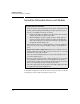
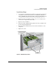

Table Of Contents
- 1: Overview
- 2: Hardware Installation
- 3: Getting Started
- Initial Configuration
- Configure the Steelhead Application
- A: EMC Regulatory Statements
- B: Waste Electrical and Electronic Equipment (WEEE) Statements
- C: Hardware Components
- D: Software Components

2-10
Hardware Installation
Install the Extended Services zl Module
Install the Extended Services zl Module
To install the module into a switch, the switch can be powered on or off. The
following procedure assumes the switch is powered on.
Installation Precautions
■ Static electricity can severely damage the electronic components on the
module. When handling and installing the module, follow these proce-
dures to avoid damage from static electricity:
• Handle the module by its bulkhead or edges and avoid touching the
components and the circuitry on the board.
• When installing the module, equalize any static charge difference
between your body and the switch by wearing a grounding wrist
strap and attaching it to the switch’s metal body, or by frequently
touching the switch’s metal body.
■ The module has “low-force,” high-performance connectors. High inser-
tion forces are not necessary to install the module, and should not be
used.
■ Ensure the module is fully inserted. Press the module into the slot
until the bulkhead on the module contacts or is very close to contacting
the front face of the switch chassis.
■ Once the module is fully inserted, screw in the four retaining screws to
secure the module in place.
■ For safe operation, proper switch cooling, and reduction of electromag-
netic emissions, ensure that a slot cover is installed on any unused
module slot. For safety, no more than one slot should be uncovered at a
time, even temporarily, when the switch is powered on.
■ Check the temperature specifications for the module; different modules
have different temperature requirements.