
Riverbed® Steelhead® RiOS® Application Installation and Getting Started Guide 2010-10
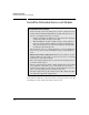
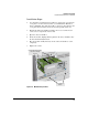
Table Of Contents
- 1: Overview
- 2: Hardware Installation
- 3: Getting Started
- Initial Configuration
- Configure the Steelhead Application
- A: EMC Regulatory Statements
- B: Waste Electrical and Electronic Equipment (WEEE) Statements
- C: Hardware Components
- D: Software Components
2-12
Hardware Installation
Install the Extended Services zl Module
The procedure to replace or remove a module is described on page C-6 in the
Web version of this document at www.hp.com/networking/manuals. Appendix
C also describes the procedure to replace the module’s Hard Disk Drive (HDD)
and the Compact Flash (CF) card.
Verify that the Module Is Installed Correctly
After you install the Extended Services zl Module, it undergoes an installation
and configuration process that may take several minutes. This happens
whether the switch is powered on after you install the module or you install
the module while the switch already has power. You can determine when this
process is completed by viewing the Module Status LED, which becomes
green when the Steelhead application has booted.
After this first bootup process, the Extended Services zl Module always
undergoes a self test when it reboots or powers on (this process takes close
to two or three minutes). Again, the LEDs help you to determine if the module
has passed the self test, as described in the table below.
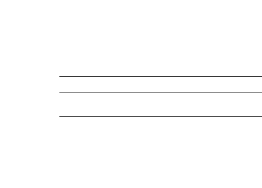
Table 2-2. LED Behavior
Error conditions indicated by the module LEDs are described in Table C-1 on
page C-2 in the Web version of this document at
www.hp.com/networking/manuals.
LED Location of
LED
Display for a Properly Installed Module
Test Switch ON briefly while the module is undergoing self test, then OFF.
Note: If the module was installed with the switch powered off, and
then the switch was powered on, the Test LED will stay ON for the
duration of the switch self test.
Figure C-4 and Figure C-5 show the location of the Test, Fault, and
Module Status LEDs on a 5400zl or 8200zl series switch,
respectively.
Fault Switch OFF
Module
Status
Switch The LED goes ON as soon as the module is installed and the switch
is powered on, and stays ON.
Module
Status
Module The LED flashes green while the OS is initializing and stays ON
when the Service OS or Steelhead Application is ready.
Figure 2-1 shows the location of all module LEDs.