HP Survivable Branch Communication zl Module powered by Microsoft Lync™ Installation and Getting Started Guide
HP Survivable Branch Communication zl Module powered by Microsoft Lync™ November 2010 Installation and Getting Started Guide
© Copyright 2010 Hewlett-Packard Development Company, L.P. The information contained herein is subject to change without notice. All Rights Reserved. This document contains proprietary information, which is protected by copyright. No part of this document may be photocopied, reproduced, or translated into another language without the prior written consent of HewlettPackard.
Contents 1 Hardware Installation Overview of the SBM . . . . . . . . . . . . . . . . . . . . . . . . . . . . . . . . . . . . . . . . . . . . 1-1 SBM Hardware . . . . . . . . . . . . . . . . . . . . . . . . . . . . . . . . . . . . . . . . . . . . . . 1-2 SBM Operating Systems (OSs) . . . . . . . . . . . . . . . . . . . . . . . . . . . . . . . . . . 1-3 Update the Switch Software . . . . . . . . . . . . . . . . . . . . . . . . . . . . . . . . . . . . . . . 1-5 Set the HP zl Switch Time . . . . . . . . . . . .
A EMC Regulatory Statements U.S.A. - FCC Class A . . . . . . . . . . . . . . . . . . . . . . . . . . . . . . . . . . . . . . . . A-1 Canada . . . . . . . . . . . . . . . . . . . . . . . . . . . . . . . . . . . . . . . . . . . . . . . . . . . . A-1 Australia/New Zealand . . . . . . . . . . . . . . . . . . . . . . . . . . . . . . . . . . . . . . . A-1 Japan - VCCI Class A . . . . . . . . . . . . . . . . . . . . . . . . . . . . . . . . . . . . . . . . A-2 Korea . . . . . . . . . . . . . . . . . . . . . . . . .
1 Hardware Installation Overview of the SBM The HP Survivable Branch Communication zl Module (SBM) powered by Microsoft LyncTM is a branch office survivable voice gateway for the Microsoft Lync solution. The SBM includes a Windows Server 2008 R2 that runs as the base OS. Running on this server, is a Microsoft Lync Server 2010 that integrates with the main office Standard or Enterprise Lync Server Pool and handles services for the branch office.
Hardware Installation Overview of the SBM Table 1-1.
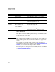
Hardware Installation Overview of the SBM Module Shutdown button Module Locator LED HDD and Network activity LEDs Management port USB port PCIe slot 1 FXO/FXS card PCIe slot 2 Module Status LED E1/T1 card Figure 1-1.
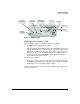
Hardware Installation Overview of the SBM Hard DISK (HD) ONE Integrated Application Compact Flash (CF) Service OS Figure 1-2. Module Operating System and Application Note 1-4 The printed version of this document contains the basic information needed to get you started using the module. It also contains EMC Regulatory Statements (Appendix A) and Waste Electrical and Electronic Equipment (WEEE) Statements (Appendix B). Appendices C and D are only in the Web version of this document at www.hp.
Hardware Installation Update the Switch Software Update the Switch Software If you need to install the HP zl switch, refer to the Installation and Getting Started Guide for the HP ProCurve Series 5400zl Switches shipped with the switch or at www.hp.com/networking/manuals. Before installing the module, you must update the HP zl switch software to version K.14.60 or later. (Visit the HP Web portal at www.hp.com/networking to check the version number of the latest SBM-compatible software.
Hardware Installation Update the Switch Software Note If you need to abort this command or another, press either [Ctrl-C] or [Ctrl-Z]. Both abort the command, but [Ctrl-Z], unlike [Ctrl-C], does not provide any message indicating that the command was aborted. 3. After the file has finished copying, you should see the prompt again as shown in Figure 1-3. Figure 1-3. HP zl Switch CLI—Software Copied 4.
Hardware Installation Set the HP zl Switch Time You should see the following output. Figure 1-4. HP zl Switch CLI—show version Output Set the HP zl Switch Time The SBM gets the current time from the HP zl switch in which it is installed. Important Because the domain join and other functions will fail unless the SBM time matches the domain controller's, the HP zl switch must be set with the correct time.
Hardware Installation Set the HP zl Switch Time 4. Configure the SNTP server IP address (either the domain controller or an SNTP server with the correct time): Syntax: sntp server priority 1 Replace with the reachable IP address of the domain controller or SNTP server. 5. Set the timezone: Syntax: time timezone <-780 - 840> The switch calculates the time zone offset in minutes. For example, to specify GMT +1, type 60. 6.
Hardware Installation Set the HP zl Switch Time 2. Set the date: Syntax: clock set
- Replace
- with the two-digit date, two-digit month number, and four-digit year. For example, 05/24/2010 3. Set the time (which must be within a few minutes of the domain controller’s time): Syntax: clock set Replace with the two-digit hour in the 24-hour clock, two-digit minute, and two digit seconds. For example, 10:09:35. 4.
Hardware Installation Install Telephony Cards Install Telephony Cards You must install your HP PCIe telephony cards on the SBM before you install the module into the switch. For instructions, please see the PCIe Analog Card (FXO or FXS) and Digital Card Installation Instructions shipped with these cards. Install the SBM Installation Precautions 1-10 Static electricity can severely damage the electronic components on the module.
Hardware Installation Install the SBM The SBM is hot-swappable; that is, the HP zl switch can be powered on or off when you install the module within it. The following procedure assumes the switch is powered on. Installation Procedure Note Install your HP PCIe telephony cards on the SBM before you install the module into the switch. 1. Use a Torx T-10 or flat-bladed screwdriver to unscrew the screws in the cover plates over the slots where you will install the SBM.
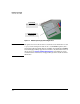
Hardware Installation Install the SBM Insert module into the guides and slide in until fully inserted. Open extractor handles. Figure 1-5. Module being installed The procedure to replace or remove a module is described on page C-7 in the Web version of this document at www.hp.com/networking/manuals. Verifying That the Module Is Installed Correctly If you have installed the SBM in a powered off HP zl switch, power up the switch. After the switch powers up, the SBM will begin to power up.
Hardware Installation Install the SBM After this first boot up process, the SBM always undergoes a self test when it reboots or powers on (this process takes closer to two or three minutes). Again, the LEDs help you to determine if the module has passed the self test, as described in the table below. Table 1-2. LED Behavior LED Location of LED Display for a Properly Installed Module Test Switch ON briefly while the module is undergoing self test, then OFF.
Hardware Installation Environmental Specifications Environmental Specifications Figure 1-6. Environmental Specifications and Maximum Modules Temperature Operating 0C to 45C (32F to 113F) Non-Operating a -10C to 65C (-10F to 149F) Relative humidity (non-condensing) 15% to 90% at 40C (104F) 15% to 90% at 65C (149F) Maximum altitude 3.0 km (10,000 ft) 4.6 km (15,000 ft) a.
2 Getting Started Initial Configuration At this point, your HP zl switch should be installed, and the SBM should be installed within it. This section guides you through the next steps that must be completed before you can launch the Setup Wizard. Obtain IP Connectivity to the SBM You have two choices for reaching the SBM the first time that you launch the Setup Wizard: You can initially access the SBM on its default management IP address, 192.168.2.10/30.
Getting Started Obtain IP Connectivity to the SBM Determine the SBM’s IP Address You must now determine the IP address at which to contact the SBM. (Sometimes the SBM receives a fixed DHCP address from a reservation, but you should still verify that the proper address has been received.) Note You must have management access to the HP zl switch in which the SBM is installed to complete these steps. If you are not in charge of managing the switch, hand this section off to the HP switch administrator .
Getting Started Obtain IP Connectivity to the SBM You should see output such as that shown below. Figure 2-2. SBM CLI—show ip Command Output Record the IP address for the Internal Ethernet Port 2: _______________________________________________________________ Also record the SBM’s default hostname, which is its serial number: _______________________________________________________________ 4. If the SBM has not received a valid IP address (for example, it has a selfassigned address beginning with 169.
Getting Started Obtain IP Connectivity to the SBM 5. Otherwise, verify the SBM’s connectivity by pinging an IP address in the data center such as the domain controller. Also ping your management station. hostzlswitch(hp-sbm-branch-C:win)# ping 6. When you have verified connectivity, exit the SBM CLI. hostzlswitch(hp-sbm-branch-C:win)# exit hostzlswitch(hp-sbm-branch-C)# exit You can now move to “Access the Setup Wizard” on page 2-6. Set an IP Address Follow these steps: 1.
Getting Started Obtain IP Connectivity to the SBM 5. Either reinitiate DHCP (if it has failed and you have corrected the problem) or set a static IP address: • DHCP—Enter this command: hostzlswitch(hp-sbm-branch-C:eth-2)# ip address dhcp • Static IP address—Enter these commands: hostzlswitch(hp-sbm-branch-C:eth-2)# ip address hostzlswitch(hp-sbm-branch-C:eth-2)# ip defaultgateway For example: hostzlswitch(hp-sbm-branch-C:eth-2)# ip address 10.1.1.50 255.
Getting Started Access the Setup Wizard Access the Setup Wizard On your management station (which must have connectivity to the SBM]), open a Web browser. Supported Web browsers include: Note Windows Internet Explorer (IE) 7 Windows IE 8 Mozilla Firefox 3.6 It is very important that your browser accept and run scripts initiated by the Setup Wizard. Typically, this will not be a problem after you join the SBM to the domain (as long as your station is also a member of the domain).
Getting Started Access the Setup Wizard Figure 2-3. IE 7—Certificate Security Warning Window 2. Originally, the SBM uses a self-signed certificate, so your browser does not trust it. Click Continue to this website (not recommended). 3. You may be prompted to enter a username and password. For now, you must log in to the SBM as a local Administrator. (Your data center contact has given you domain user credentials, but do not use those at this point in the process.) The username is SBMAdmin.
Getting Started Access the Setup Wizard Reset Password You will now configure a new password to protect the local Administrator access to the Windows Server 2008 R2 OS that runs on the SBM. Figure 2-4. Setup Wizard—Reset Password Page 2-8 1. For User Name, type SBMAdmin. 2. For Old Password, type the default password (P@ssw0rd). 3.
Getting Started Access the Setup Wizard Note Someone who logs in with these credentials has administrative access to all local tools on the SBM. However, this user might not have permission to complete all tasks required for setting up the SBM. (You will log in as a domain user later.) 4. When you have set the new password, click Submit. You are prompted to log in again. Figure 2-5. Setup Wizard—Connection to Window For Username, type SBMAdmin and for Password, type the new password.
Getting Started Access the Setup Wizard Figure 2-6. 4. Click Sites. 5. Type the exact address at which you will contact the SBM initially—for example, https://. Figure 2-7.
Getting Started Access the Setup Wizard 6. Click Add. The address will move to the Websites list. Figure 2-8. IE Internet Options > Security Window (Site Added) 7. Click Close. 8. Click OK. Return to the steps in “Access the Setup Wizard” on page 2-6.
Getting Started Access the SBM via Remote Desktop Protocol (RDP) Access the SBM via Remote Desktop Protocol (RDP) As a final step in verifying that the SBM is installed, connected, and ready to configure, access it via RDP. 1. From your management station’s Start menu, select Programs > Accessories > Remote Desktop Connection. (The path might vary slightly based on your OS and settings.) Figure 2-9. 2. Remote Desktop Connection Window For Computer, type the SBM’s IP address and click Connect.
Getting Started Access the SBM via Remote Desktop Protocol (RDP) Figure 2-10. Remote Desktop Connection Error 4. When prompted, log in as Administrator, using your new password. 5. The desktop for the Windows Server 2008 R2 running on the SBM is displayed.
Getting Started Access the SBM via Remote Desktop Protocol (RDP) Figure 2-11. SBM Remote Desktop 6. Click Start > Control Panel. 7. Click System and Security and then System. 8. In this window, you can see your SBM’s computer name (which is its serial number, by default) as well as its current software version. You can also click Online help to be directed to services and tech support resources.
Getting Started Access the SBM via Remote Desktop Protocol (RDP) Figure 2-12. Remote Desktop—System Window To return to the Setup Wizard, you can either: Note Log out of the Remote Desktop and return to your Web browser session. Click the Manage HP SBM shortcut on the desktop. (If prompted to add about:blank to your trusted sites, do so. If prompted that you are going to view pages over a secure connection, click OK.
Getting Started Access the SBM via Remote Desktop Protocol (RDP) 2-16
EMC Regulatory Statements A EMC Regulatory Statements U.S.A. - FCC Class A This equipment has been tested and found to comply with the limits for a Class A digital device, pursuant to Part 15 of the FCC Rules. These limits are designed to provide reasonable protection against interference when the equipment is used in a commercial environment.
EMC Regulatory Statements Japan - VCCI Class A Korea Taiwan European Community Declaration of Conformity This product is designed for operation with HP switches that have zl module slots. Refer to the Declarations of Conformity included in the Installation Guides for those products.
Waste Electrical and Electronic Equipment (WEEE) Statements B Waste Electrical and Electronic Equipment (WEEE) Statements Disposal of Waste Equipment by Users in Private Household in the European Union This symbol on the product or on its packaging indicates that this product must not be disposed of with your other household waste.
Waste Electrical and Electronic Equipment (WEEE) Statements Laitteiden hävittäminen kotitalouksissa Euroopan unionin alueella Jos tuotteessa tai sen pakkauksessa on tämä merkki, tuotetta ei saa hävittää kotitalousjätteiden mukana. Tällöin hävitettävä laite on toimitettava sähkölaitteiden ja elektronisten laitteiden kierrätyspisteeseen.
Waste Electrical and Electronic Equipment (WEEE) Statements Smaltimento delle apparecchiature da parte di privati nel territorio dell'Unione Europea Questo simbolo presente sul prodotto o sulla sua confezione indica che il prodotto non può essere smaltito insieme ai rifiuti domestici. È responsabilità dell'utente smaltire le apparecchiature consegnandole presso un punto di raccolta designato al riciclo e allo smaltimento di apparecchiature elettriche ed elettroniche.
Waste Electrical and Electronic Equipment (WEEE) Statements Descarte de Lixo Elétrico na Comunidade Européia Este símbolo encontrado no produto ou na embalagem indica que o produto não deve ser descartado no lixo doméstico comum. É responsabilidade do cliente descartar o material usado (lixo elétrico), encaminhando-o para um ponto de coleta para reciclagem.
Hardware Components Front Panel Buttons, LEDs, and Connectors C Hardware Components Front Panel Buttons, LEDs, and Connectors This section describes the different buttons, LEDs, and connectors on the front panel of a module: ■ Caution Module Shutdown button—This button is used to shut down the module. A message is written to the switch log to indicate the module has shut down.
Hardware Components Front Panel Buttons, LEDs, and Connectors The following table describes the LEDs on the front panel. Table C-1. Module LEDs Module LED State Module Statusa (green/ orange) Meaning When the module is first installed, this LED follows the following sequence: 1. Green for ~15s - The module has power. 2. Orange for ~11s - Testing the LED. 3. Green for ~4s - Starting self-test. 4. Orange for ~30s - Self-test in progress. 5. Off - The module is booting the OS.
Hardware Components Upper Deck Upper Deck The module includes an upper deck PCA, which provides two PCIe slots. These slots support two user-installable telephony PCIe cards. For information on installing these cards, please see the insert shipped with these cards. Lower Deck The module also includes a lower deck, which supports the compact flash card and the 250 GB disk drive.
Hardware Components Serial Numbers Serial Numbers Serial numbers are required when contacting HP or a reseller for warranty assistance or for coverage under a service agreement. The serial number is also the SBM’s default hostname (or computer name). For future reference, record the serial and product numbers in the warranty booklet. The product ships as a bundle.
Hardware Components Serial Numbers Module serial number N: SGxxxxxxxx Figure C-2.
Hardware Components Switch LEDs Switch LEDs The following figures show the Test, Fault, and Module Status LEDs on the switches the module can be installed in. Test LED Fault LED Module Status LEDs Figure C-4. Test, Fault, and Module Status LEDs on a Series 5400zl switch Fault LED Test LED Module Status LEDs Figure C-5.
Hardware Components Replacing or Removing a Module Replacing or Removing a Module It is highly recommended that the HP Extended Services zl Module shutdown before replacing or removing it.
Hardware Components Field Replaceable Units (FRUs) Caution For proper cooling and reduction of electromagnetic emissions, ensure that a slot cover is installed on any unused slot. In an operational chassis, an unused slot should be covered if it is not used for more than 2 minutes.
Software Components Updating HP zl Switch Software D Software Components Updating HP zl Switch Software The SBM requires switch software version K.14.60 or later to be installed in the switch. When an update is needed, use the following steps to update the switch software: 1. Visit the HP Web portal at www.hp.com/networking to check the version number of the latest module-compatible software. 2. Check the version number of the software installed on the switch.
Software Components Updating the Service OS Updating the Service OS There are two ways to update the Service OS: Note ■ Via FTP: used when a local FTP server is accessible from the module ■ Via USB: used when a local FTP server is not accessible from the module The process of updating the Service OS is faster if the switch is accessed via Telnet or SSH; the serial console slows down the writing of characters to the screen, causing a significantly slower installation speed, especially if the switch co
Software Components Updating the Service OS 7. Boot the Service OS (optionally, boot the ONE-app, if one is installed): hostzlswitch(svcs-mod-E:SvcOS)# boot ServiceOS Changing boot from CF Service OS to Service OS. System will be rebooted. Do you want to continue [y/n]? y Rebooting 8.
Software Components Device Disable Device Disable The SBM offers improved security and reliability. In case there is no physical security on the chassis, the USB and the shutdown button can be disabled to prevent unauthorized or undesired access. Both the USB and the shutdown button are enabled by default. The USB is disabled during boot. Use the device command without an argument to show the devices enabled/ disabled.
Index C L Command Line Interface (CLI) … 1-1 show version … D-1 shutdown … C-1, C-7 Switch … C-2, D-1 Compact Flash … 1-3 LED Behavior … 1-2, 1-13 Fault … 1-13 HDD Activity … C-2 meaning … C-2 Module Locator … C-2 Module Status … 1-13, C-2 Network Activity … C-2 State … C-2 Switch … C-6 Test … 1-13 D device disable … D-4 DNS server set … 2-5 E M EMC Regulatory Statements … A-1 environmental specifications … 1-14 management port … C-1 Module front panel See front panel F Field Replaceable Units (FRU
U update switch software … 1-5 Upper Deck … C-3 USB slot HP zl switch … 1-5 SBM … C-1 W warranty … 1-2 Waste Electrical and Electronic Equipment (WEEE) Statements … B-1 Z zl Switch … C-6 2 – Index
center Connection Manager Controller Management and Configuration
Technology for better business outcomes To learn more, visit www.hp.com/networking © Copyright 2010 Hewlett-Packard Development Company, L.P. The information contained herein is subject to change without notice. The only warranties for HP products and services are set forth in the express warranty statements accompanying such products and services. Nothing herein should be construed as constituting an additional warranty. HP will not be liable for technical or editorial errors or omissions contained herein.