
TMS zl Management and Configuration Guide ST.1.1.100226


7-107
Virtual Private Networks
Configure an IPsec Site-to-Site VPN with IKE
To learn about creating Bypass and Deny policies, see “Configure Bypass
and Deny IPsec Policies” on page 7-352.
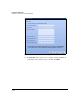
7. For Position, type a number.
The position determines the order in which the TMS zl Module processes
IPsec policies. The module processes the policy with the lowest value first
(for example, position 1 before position 2). The position matters most
when policies have overlapping traffic selectors. In this case, assign the
highest position (lowest value) to the IPsec policy with the most specific
traffic selector.
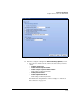
Note that you can specify a position that is already used by another policy.
The new policy is inserted above the former policy. You can use the arrow
icons in the Tools column in the VPN > IPsec > IPsec Policies window to
rearrange policies. Remember the policy at the top of the display is the
first policy processed.
A default IPsec policy prevents all traffic from being encrypted by the VPN
engine; therefore, all IPsec policies that you configure must have a higher
priority than this default policy.
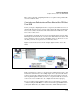
Next, you configure the VPN traffic selector, which determines which traffic
will use the VPN tunnel. For example, the selector might specify all IP traffic
between 192.168.2.0/24 (a local network) and 192.168.3.0/24 (a remote net-
work). For a policy with the Apply action, the selected traffic is the traffic that
is sent and received (and secured) on the IPsec SA.
Note If your traffic selector will include management traffic, you must configure a
Bypass policy with top priority that selects the management traffic, or you will
be locked out of the Web browser interface. If you do lock yourself out, reboot
the module, but DO NOT SAVE the configuration.
See “Configure Bypass and Deny IPsec Policies” on page 7-352.
If your traffic selector will include traffic that is also selected for NAT, you
must create a NAT exclusion policy. See “Exclusion NAT Policies” in
Chapter 5: “Network Address Translation.”
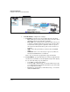
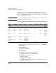
Refer to Figure 7-94 for help in configuring the next settings.