
TMS zl Management and Configuration Guide ST.1.1.100430

1-79
Overview
Feature Interaction
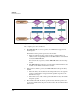
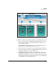
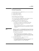
Figure 1-23. Traffic Flow in Routing Mode
When Device A wants to send traffic to Device C, the following steps occur:
1. Device A sends the frame to a TMS zl Module MAC address because the
traffic requires routing and the module IP address on VLAN_7 is the
device’s default gateway.
The TMS zl Module might or might not have a unique MAC address for
this IP address. See “TMS VLANs Rules” on page 1-9.
2. The host switch receives the frame on C1, which is untagged for VLAN_7.
3. The switch forwards the frame on the TMS zl Module’s data port, which
is tagged for VLAN_7, so the switch adds the tag.
4. The TMS zl Module filters the traffic as described in the section above,
applying Zone1-to-DMZ access policies as well as other features. The
module knows that the traffic’s source zone is Zone1 because the traffic
arrived tagged for VLAN_7. In this example, Device C is in a TMS VLAN,
so this VLAN's zone is the destination zone.