HP ProCurve Threat Management Services zl Module © Copyright 2009 Hewlett-Packard Development Company, L.P. The information contained herein is subject to change without notice. All Rights Reserved. This document contains proprietary information, which is protected by copyright. No part of this document may be photocopied, reproduced, or translated into another language without the prior written consent of Hewlett-Packard.
Table of Contents 1.0 Purpose............................................................................................................................................ 5 2.0 Intended Audience .......................................................................................................................... 5 3.0 Objectives ....................................................................................................................................... 5 4.0 Prerequisites ......................
Network Diagrams .................................................................................................................. 61 10.1 10.2 Switch Configuration .............................................................................................................. 63 10.3 Management VLAN and Zone ............................................................................................... 65 10.4 Zones to VLANs ...................................................................................
1.0 Purpose The purpose of this technical guide is to provide a technical understanding of the expected use cases for the HP ProCurve Threat Management Services (TMS) zl Module in more complex networking environments. It is intended to assist in the sale, design and implementation of HP ProCurve security solutions using the TMS zl Module and also provides some specific, technical “how to” configuration information. 2.
5.0 Skills The individual following this guide should possess the following skills: Basic understanding of Stateful Packet Inspection (SPI) firewalls, Intrusion Detection and Prevention Systems (IDSs/IPSs), and Virtual Private Networks (VPNs) Familiarity with clustering and other High Availability (HA) technologies like Virtual Router Redundancy Protocol (VRRP) Ability to translate security policy requirements into security controls 6.
6.1.1 Zone-Based Firewall The TMS zl Module is specifically a zone-based, rather than a traditional interface-based, firewall. Zone-based firewalls have greater granularity, more flexibility, and are conceptually simpler in their security control model. The TMS zl Module uses zones to control traffic. Zones are logical groupings of TMS VLANs that have similar security needs or levels of trust that organize the network into different security regions.
6.1.2 Network Address Translation (NAT) Network Address Translation (NAT) is the process of modifying IP address information in packet headers in order to map one address space to another. Itis a very common function for firewalls due to many networks using RFC 1918 private IP addresses, e.g. 10.x.x.x, 172.16-31.x.x, 192.168.x.x on the inside of the firewall and a small block of publicly routable registered IP addresses on the outside of the perimeter firewall. 6.1.
• l2tp - The Layer 2 Tunneling Protocol (L2TP) ALG • msn - The MSN ALG supports the following functionalities of Microsoft Instant Messenger 7.
detected by default and cannot be disabled by the administrator. Other attack checking, such as SYN Flooding and WinNuke, among others, may be enabled or disabled by the administrator. 6.2 Network Intrusion Detection / Prevention System A network intrusion detection system (IDS) is an independent platform that detects and logs malicious activity, or intrusions, such as viruses, worms, trojans, denial of service attacks, and attempts to crack into computers.
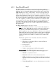
• • Reusability of firewall policies, for example in the VPN control Selective application of IPS by individual firewall rules The following diagram shows the order of processing by the three controls on traffic incoming to a TMS zl Module zone interface: Figure 1: TMS zl Module Interface Inbound Processing Flow Packets inbound on an interface are first processed by the firewall. If they are permitted by the security policy rules, then they will pass to the VPN Gateway for decryption, if necessary.
As with inbound, the traffic is first processed by the firewall. If permitted by the security policy rules, it is then passed to the Intrusion Prevention System for deeper inspection prior to being optionly encrypted by the VPN Gateway. 6.5 Named Objects Another feature of the TMS zl Module that is used across all the integrated security platform is “Named Objects.” The TMS zl Module supports named objects for greater ease of configuration.
o Time of day—the start and end times within the day For example, rather than manually specify the IP address of your Web server in multiple policies, you can create an object named WebServer with the Web server’s IP address. You can then specify the WebServer object every time that you create a policy for controlling access to the Web server. If the IP address of the Web server changes you can edit the address object, and the change will propagate through all of the policies that include the object.
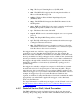
7.0 Common TMS Security Control Points There are three common security control points where it is anticipated that many enterprise environments will wish to deploy the HP ProCurve Threat Management Services zl Module: 1. At the perimeter of the enterprise network where it interfaces with the Internet and/or business partner networks to protect from untrusted external networks 2.
Figure 3: Perimeter Security Control Point At this control point, as shown in Figure 3, the HP ProCurve Threat Management Services zl Module can: • Restrict inbound traffic with the firewall feature to only that which is absolutely necessary for the services and applications the organization wishes to intentionally expose, perform NAT, and restrict outbound traffic determined necessary to conduct business.
7.1.1 Firewall Typical controls implemented by firewalls at the perimeter include, but are, of course, not limited to: • Performing one-to-one NAT from registered, publicly routable IP addresses in the External zone to private, non-publicly-routable IP addresses for the Web Server, FTP Server and Proxy E-Mail Server in the DMZ zone • Permitting Simple Mail Transfer Protocol (SMTP) traffic from the External zone to the Proxy E-Mail Server in the DMZ zone.
7.1.2 IDS/IPS The security controls implemented by an IDS or IPS placed at the perimeter depend on whether the IDS or IPS is placed on the “outside” (unprotected side) or “inside” (protected side) of the perimeter firewall. Note: Implementing the best practice of IDS outside the firewall and IPS inside the firewall requires an additional TMS zl Module configured in monitor mode to act as the IDS outside the firewall provided by the first TMS zl Module that is also providing the IPS inside the firewall. 7.
Directory Traversal Attempt, Windows FTP Guest Account, etc. HTTP-specific: PHPNuke Forum SQL Insertion, Access to Alexa Spyware Site, BEA WebLogic URL JSP Source Code Disclosure, ColdFusion File Disclosure, etc. SQL-specific: IIS BattleAxe Forum SQL Injection, Oracle 9iAS Portal Demo SQL Injection, All-In-One Control Panel SQL Injection, etc.
7.1.3 VPN Gateway The TMS zl Module is shown in Figure 4 acting as a Remote Access VPN Gateway for a teleworker, providing a secure connection over the Internet. Figure 4: Perimeter Security Control Point Remote Access VPN Figure 5 shows the TMS zl Module performing as a site-to-site VPN Gateway for a branch office, also providing a secure connection over the Internet.
Figure 5: Perimeter Security Control Point site-to-site VPN Typical controls implemented by VPN Gateways are: 7.
Figure 6: Data Center Compartmentalization Security Control Point A security enclave is an even higher security area within the enterprise network. The conversion of the data center into an enclave is simply one of the more obvious applications of this concept. In the above figure, the data center has been made into an enclave with compartments within the enclave.
LDAP traffic bound for the Domain Controllers, SQL traffic aimed at the Database Servers, and any application-specific traffic intended for the Application Servers. • Employ the intrusion detection / prevention feature to either alert administrators or interrupt suspicious traffic signatures, protocol-specific anomalies and general network anomalies appearing within conversations that pass the data center enclave firewall or between the compartmentalized zones within the data center.
Permit Simple Network Management Protocol (SNMP, UDP/161) Apps, SQL, AD, SMB, Management External Permit Server Message Block (SMB, UDP/135-139, 445 and TCP/135-139, 445) Management SMB Permit Active Directory (AD, UDP/42, 53, 88, 135, 137, 138, 389, 445, 1512 and TCP/42, 53, 88, 135, 137, 139, 389, 445, 636, 1512, 3268, 3269, AD-fixed-port, FRS-fixed-port) Management AD Note: DS-fixed-port and FRS-fixed-port require registry changes on all Global Catalog, Domain Controller and Member Servers to
opened.
SMB, SQL Scenario 2 - Typical firewall controls for a data center as a single, monolithic enclave, as in Figure 7, above: Action Description From Zone (Source) To Zone (Destination) Permit Simple Network Management Protocol (SNMP) Traps (UDP/162) External Internal Permit Server Message Block (SMB, UDP/135-139, 445 and TCP/135-139, 445) External Internal Permit Active Directory (AD, UDP/42, 53, 88, 135, 137, 138, 389, 445, 1512 and TCP/42, 53, 88, 135, 137, 139, 389, 445, 636, 1512, 3268, 3269,
7.2.2 IDS/IPS Similar to the Perimeter firewall placement scenario, IDS/IPS can be deployed in data center placements as an IDS and IPS with a minimum of two modules. The IDS, with a module in monitor mode, is configured to monitor a baseline of intrusion activity at the outside of the firewall. The IPS, running on the module shown above in routing mode, is configured to check for protocolspecific intrusion signatures, generic per-protocol anomalies and general IP protocol anomalies.
7.2.3 VPN Gateway The TMS zl Module is shown in Figure 8 performing as a site-to-site VPN Gateway for a strategic business partner, providing an additional layer of security to an extranet connection. The perimeter firewall is simply a passthrough point in the VPN tunnel’s path. Any NAT performed by the perimeter firewall is dealt with through the use of the standard NAT Traversal (NAT-T) option.
In this example, the application servers in the data center, which process PCI data, are only accessible from outside of their enclave (e.g. from the system administrator at the headquarters campus) via a VPN connection into the PCI security enclave within the data center, strictly limiting the scope of PCI compliance. Typical controls implemented by VPN Gateways are: 7.
Figure 10: Wired/Wireless Compartmentalization / Data Center / Perimeter Security Control Point Note: While multiple LAN switches are depicted above for visual clarity, the above topology could be implemented via a single physical switch using separate VLANs for each of the “clouds.
Figure 11: Wired/Wireless Compartmentalization / Data Center Compartmentalization / Perimeter Security Control Point Note: As in the previous figure, multiple LAN switches are depicted above for visual clarity but the above topology could be implemented via a single physical switch using separate VLANs for each of the “clouds” and two different VLANs for the two distinct security zones shown within the Data Center “cloud.” Figure 11, above, shows a variation on the previously shown scenario.
Figure 12: Multinational Compartmentalization Security Control Point(s) As shown above, in Figure 12, a multinational corporation might choose to compartmentalize its network along geographical or continental boundaries.
Figure 13: Campus Compartmentalization Security Control Point(s) The TMS zl Module, of course, doesn’t have to simultaneously fulfill all of its possible roles. In Figure 13, above, a single TMS zl Module is acting as both traditional perimeter security and is compartmentalizing a college campus network into the campus administration portion, the business college portion, and the computer science college portion where higher-risk activities such as virus and other malware research might be conducted.
Figure 14: Functional Compartmentalization Security Control Point(s) The example shown above in Figure 14 is a layered security variation on the Perimeter/Compartmentalization college campus network scenario shown previously. In this example, a corporate network is protected by one TMS zl Module at its perimeter with that module’s Internal zone being the same VLAN as the External zone of an additional TMS zl Module that provides another layer of security control to the corporate network.
A common example is the typical n-tier database-driven web site. The web server front-end (often Apache or IIS) sits in the DMZ security zone. The database server (frequently Oracle, mySQL or SQL Server) is sited within the data center security zone or a more specific database servers security zone within multiple zones in the data center.
the modification, regardless of the theoretical source and destination security zones. See Chapter 6, “Intrusion Detection and Prevention,” of the HP ProCurve Threat Management Services zl Module Management and Configuration Guide for detailed information on how to enable the intrusion subsystem, register your signature update subscription, disable individual signatures and tune protocol-specific anomaly settings.
In addition to tunnels providing secure access for administrators of senstive information processing hosts as previously shown in Figure 9: Data Center Security Control Point Internal VPN, the tunnels from the remote sensitive information enclaves back to the data center can also be joined into this protected network.
8.0 Deployment Considerations 8.1 Overview To develop the specific configuration requirements to implement the TMS zl Module to secure a customer’s network, some level of a company security policy is required. Since situations will arise where existing security policies may be non-existent or not extensive enough, this section will provide basic guidelines to assist in creating a set of rules that will be used to develop a security design to be implemented on the TMS zl Module.
effective, a security policy needs to include multiple other areas of security such as proper door locks on IT equipment rooms (physical) or using a Kensington lock on all laptops (procedural). • Although not infrastructure related, proper authentication policies should be in place to ensure access to network resources can be properly controlled and logged. This should include a requirement for each user to have a unique login account.
• • • High Risk – Information assets noted in compliancy legislation (HIPAA, PCI, etc.) that require prevention of improper disclosure or financial penalties in the event of such disclosure. Information may also be considered “high risk” if disclosure could cause severe damage to the organization or if there are other company policies that deem it to be considered “sensitive” such as payroll, personnel, financial and legal information.
8.4 Correlating Network Listeners with Server Processes Now that we have a list of applications and the servers that they run on, the next step is to identify the actual network communication specifics used by each application. Any existing application or network documentation should be gathered and consulted to assist in identifying network details and interactivity between servers. The software manufacturers’ web sites may also provide additional information that can be consulted for this process.
This is a sample of what TCP View will show for each process using TCP/IP on the server: Next, determine the related application or purpose of the specific process.
you can create separate access policies for controlling the traffic to and from each VLAN. • If you plan to create many different policies for different TMS VLANs, it might be easier to associate the VLANs with different zones. For example, you could associate VLANs in your private network with three separate zones: Zone1 contains the server VLAN 10; Zone2 contains user VLAN 20, which is for regular employees; and Zone3 contains user VLAN 30, which is for guests.
Developing specific Virtual Private Network (VPN) requirements will not be addressed in this document but typically encompass identifying network traffic paths that require encryption. The details gathered from research and discussion with the customer IT staff will provide the foundation for identifying a need (or not) for VPNs to properly protect this customer’s information assets.
this implementation. The Firewall Rules tab of the “Company Information Assets” spreadsheet in Appendix B can be used as a reference and to capture the requirements for each rule. Every cell should be completed for all columns for each Information Asset including the appropriate TMS Zone identified earlier in this section. Again, on completion of this step, make sure to review these rules with the customer IT staff for confirmation of accuracy and completeness.
9.0 Installation and Preparation of the TMS zl Module In brief review, we have gathered a conceptual understanding of the TMS zl Module, we have a more in-depth understanding of common placement scenarios for the TMS zl Module, we have gained an awareness of HP ProCurve best practices recommendations, and we have stepped through a discovery and planning methodology accounting for different placement scenarios and features. We are now ready to physically install and begin configuring the module(s). 9.
This is the show modules command run from the serial console session. Note that devices in Slot C and G show “Failed.” This is the show modules command run from an SSH remote management session. Note that devices in Slot C and G show “Failed.” For specific steps on updating switch software, see Appendix D - Updating Switch Software.
9.1.2 Physical Installation As previously demonstrated, if the TMS zl Module is installed prior to updating the switch software to an image that supports it, the module will power up but will be inaccessible until the switch software is updated and the chassis rebooted. HP ProCurve recommends that the switch software be updated to a supported image prior to physical installation.
engage. Once the contacts have engaged, use the extractor handles to finish seating the module completely and tighten the screws.
Once in the Service OS context, issue the licenses hardware-id activation command to display the activation hardware ID that will be needed, along with the product registration ID, to generate the activation license key on the My ProCurve portal. Make note of the activation hardware ID. HP ProCurve recommends copying and pasting the activation hardware ID into a text file to avoid manual transcription errors in the next step. 9.2.
The TMS zl Module is now ready for initial configuration. 9.2.5 Initial Log Settings Logging is a key factor to completing a secure configuration and provides a foundation for analyzing security events or network troubleshooting. The following should be used as a baseline log configuration for a TMS zl Module installation. Each specific installation will have different configuration needs to meet the requirements of the unique infrastructure.
System > Logging > View Log Window In this window, you can see a real-time list of events for the TMS zl Module’s operation. To filter the logs that are displayed in this window, select and clear the appropriate check boxes under Filter. For example, to see logs of minor severity, complete the following steps. 1. Under Filter, select the Severity check box. 2. Select is for the type of filter. 3. Select Minor for the filter severity. 4. Click Apply filter.
spreadsheet application such as Microsoft Excel. It is a good idea to name the log file after the date on which it was created. For example, if the log was created on November 3, 2009, type 2009-11-03.tgz. 9.2.5.2 Configure Log Settings The TMS zl Module automatically classifies events according to severity.
2. From the list, select the lowest severity level of the messages that you want to forward. 3. In the space provided, type the number of duplicate messages that you want to occur before a tally message is forwarded. Duplicate Message Text Box 4. In the space provided, type the number of seconds that you want to pass before a tally message is forwarded. Time Limit Text Box 5. Click Apply My Changes. 6. Click Save. 9.2.5.
3. For From Email Address, type the email address that will appear in the From field. This address does not need to be valid, it only needs to be in the format username@domain.tld. 4. For To Email Address, type up to three email addresses that will receive the event logs. 5. Optionally, for User Name and User Password, type the username and password of the administrator account of the email server. 6. Click Apply My Changes. 7. Click Save. 9.2.5.
3. For Address, type the IP address or FQDN of the syslog server. 4. For Port, type the port number of the syslog server. The well-known port for syslog is 514. 5. From the Facility list, select the facility from which the events will be sent. 6. Click OK. 7. Click Save. 9.2.5.5 Configure SNMP Traps SNMP traps are unsolicited messages that are sent by managed devices to alert you about specific events. For example, you can use PCM+ to manage the TMS zl Module by specifying PCM+ as a trap destination.
Add SNMPv2 Destination Window 2. For Server Address, type the IP address or FQDN of the SNMP server. For example, if you are using PCM+, you would enter the IP address or FQDN of the server running PCM+. 3. For Community Name, type the read-write (unrestricted) community name. You must enter the read-write community name that is configured on the SNMP server. 4. Click OK. 5. Click Save. To add an SNMPv3 trap destination (such as PCM+), complete the following steps: 1.
2. For Server Address, type the IP address or FQDN of an SNMPv3 server. For example, if you are using PCM+, you would enter the IP address or FQDN of the server running PCM+. 3. For Username, type the SNMPv3 username for an account on the server. This must match the username configured on the SNMP server (such as PCM+). 4. For Auth Passphrase, type the authentication passphrase for the account on the server. This must match the authentication passphrase configured on the SNMP server (such as PCM+). 5.
System > Settings > SNMP Window SNMPv1/v2c To configure SNMPv1/v2c settings, complete the following steps: 1. From the System > Settings > SNMP window, select Enable SNMPv1/v2. 2. Under Enable SNMPv1/v2, click Add another community. The Add SNMPv1/v2 Community window is displayed. Add SNMPv1/v2 Community Window 3. For Community Name, type the community name for the SNMP server. 4. From the Role list, select Manager (read/write) or Operator (read only).
6. Click Apply. 7. Click Save. SNMPv3 To configure SNMPv3 settings, complete the following steps: 1. From the System > Settings > SNMP window, select Enable SNMPv3. 2. Under Enable SNMPv3, click Add another user. The Add SNMPv3 User window is displayed. Add SNMPv3 User Window 3. For User Name, type the SNMPv3 username for the account. 4. For Role, select the role of the account: Manager (read/write) or Operator (read only). 5.
9.2.6 Ensuring Management Access Under Heavy Load Under certain heavy load operating conditions, it is possible for the in-band management traffic of the module to be “starved out,” leading effectively to loss of the management interface. This section highlights the value of prioritizing the management interface traffic as soon as possible. As with any network implementation, it is important to identify a VLAN to be used only for switch management traffic.
10.0 Configuration of the TMS zl Module Adding a TMS zl Module to an existing environment can pose certain challenges, depending on how it is done. In some environments, the TMS zl Module will be protecting new networks and interfacing these networks with the rest of the network is a relatively straightforward task. In most environments, however, we have a stable network where the TMS zl Module will be introduced to enhance the security of the network. 10.
Here are the steps we will be performing for this exercise: 1. We want to add the TMS zl Module to the switch chassis 2. We want to move the Server VLAN’s IP address from the 5406zl to the TMS zl Module 3. We want to move the Web Client VLAN’s IP address from the 5406zl to the TMS zl Module 4. We want to configure the TMS zl Module appropriately for this network.
10.2 Switch Configuration Let’s assume that the switch where the TMS zl Module is installed is running a version of software that supports the module, and the TMS zl Module is installed in Slot “D”, is running, but has not been configured. Steps to update the switch software and to physically install the TMS zl Module are covered in Section 9 and will not be repeated here. Now let’s look at our switch configuration in this state.
context by typing services d 2. Once there, we can see the variety of commands available to us from this context. Using the show command, we can see by default the TMS zl module is in Routing Mode and there are no VLAN’s assigned from the switch to the TMS zl module.
Using the show management command, we can see there are no management zones or priority VLAN identified. The show system-information command also gives us a lot of important information. The show access-policy command will allow you to see the default policies. Note that there is a policy for RIP and OSPF from the “Self” zone to every other zone and vice-versa. Note: The TMS zl Module gets its time from the switch. Remember, it is very important the time is set correctly. See Section 9.2.
The switch management IP address is in VLAN 2. We want to add the TMS zl Module to this VLAN as well. We want the switch chassis to keep its IP address, so we will associate VLAN 2 with zone1, our management zone, and allow for the switch chassis to have an IP address in the same VLAN. We then assign an IP address to the TMS zl Module for management purposes. Then configure management priority-vlan 2 to give any traffic on VLAN 2 management priority.
Here is the diagram that represents what we just configured. Our TMS zl Module’s port D1 became a tagged member of VLAN 2. The 5406zl port B1 is an untagged member of VLAN 2 and connected to an external Ethernet device. Note: Port D2 is used for High Availability and is not discussed in this section. Figure 18 From the PC in the switch management VLAN, VLAN 2, we open up a web browser with this address: https://192.168.0.254 and we immediately see a “Security Alert” dialog.
Note: If the time on the switch is not accurately set, it may cause problems in establishing an HTTPS session due to certificate incorrectly appearing to be invalid. See Section 9.2.1 for more information on this topic. Now that we have HTTPS access, we need to login as “manager” to the TMS management interface using the default password of “procurve.
We also want to disable SNMP for now by selecting Disable SNMP on the System, Settings, SNMP tab.
10.4 Zones to VLANs As discussed in Section 6, the TMS zl Module is a zone-based firewall. One question that often arises is “How do zones relate to VLANs?” The answer: VLANs must be assigned to a TMS Zone. You can add multiple VLANs to a TMS Zone. Each VLAN must have an IP address defined on the TMS zl Module to serve as the new default gateway for that VLAN. For our example, there is a one-to-one mapping between VLANs and TMS Zones although this is not a requirement.
Remove the IP address on the appropriate VLANs in the switch configuration.
Now go back and associate the appropriate VLANs to zones with the IP Addresses removed from the switch configuration.
Let’s look at the switch’s running configuration. Here we see how the TMS zl Module’s D1 port is a tagged member of each VLAN that it has an association with. In addition, we see several new feature-coordinator commands. These prevent IP address assignment on the switch’s VLANs that may end up bypassing the protection provided by the TMS zl Module. Also, there is protection against VLAN deletion.
10.5 Routing Mode 10.5.1 Firewall At the present time, we have configured the TMS zl Module with VLAN associations to zones and IP addresses for those VLANs. However, without any specified access policies in place, there is no traffic flowing between zones. Unlike some firewalls, the TMS zl Module has no “priority” setting for zones with defaults allowing higher security levels to communicate with lower security levels.
The access policies between zones are shown here. It is very important that the “User Group” be “None” as we start to add access policies. To add an access policy, click the Add a Policy… link. Because the TMS zl Module has taken over routing functionality, it is acting as a default gateway for VLANs 3 and 4. To aid in any client/server troubleshooting, we are going to add ICMP Echo access to the default gateway as long as it originates from the same subnet.
Temporarily, we’ll also allow pings from Zone5 to Zone6 and from Zone6 to Zone5 to aid any troubleshooting that we may need to do. The image below shows the command prompt of a client on VLAN 4/Zone5 which an IP address of 10.0.0.100 and a default gateway, which is the TMS zl Module, of 10.0.0.1. See Figure 21 for the diagram of this scenario.
Figure 21 We can ping the default gateway of 10.0.0.1. However, as shown in Figure 21, we know that 172.16.0.1 is the default gateway for VLAN 3 - the server VLAN. We cannot ping that IP address (see image below) because we restricted the access policy to only allow the default gateway to accept a ping if it originates from the same subnet.
The image below shows that I can ping the web server (172.16.0.50) due to my Zone5 to Zone6 access policies. I can not ping the management VLAN (192.160.0.254) as shown. Let’s add HTTP access from Zone5 (clients) to Zone6 (servers).
From our client PC where we performed the pings, we can bring up a web browser and test our access policy with a connection to the web server on zone6 (IP Address 172.16.05.50) - our web server works! In certain circumstances, the firewall administrator may not know all the protocols and ports used by an application. A useful access policy to help diagnose any problems you may have is to put a “Deny Traffic” as the last policy from Zone5 to Zone6 and enable logging.
Here we see the Zone5 to Zone6 access policies in place. The very last one is our Deny. It has an ID of 79 in our example. This is called the “ruleid” in the log. Let’s change our log message level to Warning so we can catch this particular message. For more discussion on logging configuration, refer to Section 9.2.5: Initial Log Settings.
Next, let’s try using FTP from the client. It will not work because we did not setup an access policy, but let’s assume that we were experiencing a generic application problem. With the “Deny” policy and logging enabled, we can go to the log and find out why the application is not working.
Here in the log, we can filter on a keyword of “ruleid=79”. This allows us to see what has hit the “Deny” policy. We can see that TCP port 21(FTP) traffic was dropped. While in our example, we knew that we were using FTP all along, in other cases it may not be very obvious. This policy can save you a great deal of time and troubleshooting. At this time, it would be very appropriate to click Save to save your configuration to the TMS zl Module’s “startup configuration” file.
10.5.2 IDS/IPS In this section, we’ll look at the steps needed to enable IPS functionality in a customer environment. This section assumes that the TMS zl Module was purchased with an IPS subscription service or that a separate IPS subscription service was purchased. This subscription service enables the download of signatures to the TMS zl Module. By default, the TMS zl Module looks for updated signatures every four hours. The TMS zl Module does not come with any pre-loaded signatures.
Next we associate VLAN 5 with the External zone. Let’s add a static route which says “when it doubt, send to the ISP router”.
Add the DNS server IP addresses and Domain Suffix. Add the proxy server, if applicable.
We want to add a couple of access policies from Self to External. A policy for the web proxy server and a policy for DNS. Note: for security purposes, since we are using static routes, we should delete the RIP and OSPF access polices.
Let’s enable threat detection and use the default actions – be sure to click Apply. Notice the settings: For Critical threats, the IPS will terminate the session where the critical threat was recognized. For others, it will block traffic, and others, it will simply log and allow the traffic to pass. We like more security, so let’s sacrifice a little performance to get more security by checking the full session inspection check box – Click Apply My Changes.
Click Download Now and we should not get any errors – instead we should get “Successfully completed” and a “version number.” At this point, our IPS is operational and active.
10.5.3 Internet Access for Windows Update Internet access using a private address requires an additional step – Network Address Translation, or NAT. Let’s detail this configuration by allowing our clients to access Windows Update. As a refresher, here is another look at our network diagram. Our web clients are on the 10.0.0/24 subnet, which is not publicly routable. Figure 23 We need to translate those private IP addresses to a public IP address that is on VLAN 5. Let’s setup a NAT policy.
Setup an Access Policy to the Web-Proxy Server – from Zone5, where the clients are located, to the External zone where the Internet is located.
Note: The configuration here is using default NAT configuration and will work for this example design but additional NAT configuration may be required for your configuration. For additional direction on NAT configuration, see the various sections discussing NAT in the HP ProCurve Threat Management Services zl Module Management and Configuration Guide.
10.5.4 VPN Gateway The problem: How do we protect private information that is transmitted via the public Internet? The solution: A Virtual Private Network or VPN. There are two primary use cases – the site-to-site VPN which protects traffic between two sites, such as a Main Office and Branch Office. Alternatively, a VPN can also allow remote workers to “dialin,” to use common but outdated terminology, into their workplace. These two separate needs have two separate configuration methodologies.
We will need the following information to complete the next steps: Content Value Description Internal zone VLAN(s) VLAN 2 Users inside the branch office External zone VLAN(s) VLAN 3 Zone1 VLAN(s) VLAN 4 Internet connectivity (e.g. DSL bl d ) Management VLAN for the t k Both Sites IKE preshare key (if used) ZoneX VLAN(s) Service (ports) Any Service Typical for site-to-site VPN Site A – Corporate Office TMS zl Module IP Address 172.31.31.
SITE B: We will need to add the ability to negotiate an IPsec session to our access policies. We will need to allow ISAKMP to our access policies as it performs the IPsec negotiation. We will use the IP addresses of the TMS zl Modules as our source and destination. Also, the ISP is potentially using NAT within the Internet Cloud, therefore, we should add a NAT traversal access policy as well.
SITE B: We’ve set up an HTTP access policy between the IP address ranges in our sites. IP address aggregation or summarization is important here for simplifying our configuration. This example is rather simplistic, but the idea is the same – the easier I can reference Site A and Site B in terms of IP address aggregates, the easier it will be to configure not only access policies, but IPsec as well.
SITE B: We have our firewall setup, but we do not have IPsec configuration in place yet. We start by creating an IKE policy. We specify site-to-site as the policy type and enter the TMS zl Module addresses for the Local and Remote gateways. In our example, we will be using Pre-Shared keys, so we utilize the same IP addresses for Identities. It is recommended that certificates be used for customer deployments.
SITE B: Here we select Main Mode and Preshared Key. We are just using the defaults here, but for more security, moving to DH Group 2 and the authentication algorithm of SHA-1 would be appropriate. Just remember that if you change things here, you need to configure the other TMS zl Module to match your parameters.
SITE B: Disable XAUTH and click Finish to complete configuration of the IKE policy.
SITE B: Next we move to IPsec Proposals. The image below shows what we want configured for a site-to-site deployment. Be sure to use the ESP Security Protocol. For more security, you can select a different authentication algorithm other than the default of MD5. Click OK to complete the IPsec Proposal configuration.
SITE B. Next we will specify an IPsec Policy. The IPsec Policy will determine which traffic is protected by IPsec. In most cases, our traffic selector “Action” will be Apply, the “Direction” will be Both, and the “Protocol”will be Any. Here is where using the IP address as the basis for our IPsec Traffic Selector becomes important. We want to specify IP addresses between Site B and Site A. The easier it is to specify IP addresses that correspond to these sites, the easier it is to configure.
SITE B: Here we select the IKE policy to use as well as optionally choosing to enable PFS. PFS will give more security to your network, but be sure both sides are configured the same.
SITE B: IP address pools are not needed for site-to-site VPNs, so we won’t worry about configuring it at this time.
SITE B: We don’t really have to enable any options here, but IP compression may help save bandwidth. If you are using MPLS for QoS guarantees from your service provider, using “Copy DSCP” on IPsec packets will be important. We’ve configured SiteB. Now we need to mirror that configuration for SiteA. Also, you may want to click Save at this point as well to save your work.
SITE A: This is the original TMS zl Module we’ve been using in our previous examples. We want to set up the same access policies for ISAKMP and NATTraversal.
SITE A: We setup a mirror image of the IKE policy on Site A that we did with Site B.
SITE A: We need the exact same configuration here as we did with Site B.
SITE A: Disable XAUTH.
SITE A: Moving to our IPsec proposal, we make it exactly the same as Site B.
SITE A: We have a mirror image for our Local/Remote address in our IPsec policy to the configuration on SiteB. We want to keep everything else the same.
SITE A: We want our key management to be the same as Site B too.
SITE A: No IP address pools are needed for site-to-site, so we can skip this.
SITE A: These are some optional parameters and we want to match with Site B. Now is a good time to save our work.
Now let’s do some validation A client on Site B accessing web server on Site A. What do you know, it works! Note: “NAT none” might be necessary to prevent IP-addresses that must be send through the tunnel to be NAT-ed. If this is not configured, NAT is performed before VPN traffic is put inside the IPsec tunnel. This might result in loss of traffic or traffic not being encrypted or if routing is necessary for VPN traffic.
10.5.5 Remote Access with Windows and L2TP over IPsec Let’s examine our next VPN scenario – the remote worker “dialing in” to access resources at the main office. This section will detail the TMS zl Module configuration. Detailed configuration for Windows XP and Vista clients will not be discussed in this section. For more discussion on configuration Windows and Macintosh VPN clients, see Section C in the HP ProCurve Threat Management Solution Implementation Guide.
On this screen is where we add a group. Let’s create the “VPN_User_Group”. We don’t want to add a user here, we will be doing that in our IPsec/L2TP configuration.
A “Name” can be used as an alternative way of specifying IP addresses. We want to create name to IP address mappings as in the example image. Note: With client-to-site VPN, the concept of a “Virtual IP network” is associated with a successful VPN session. For our example, this network is 10.254.254.0/24. The TMS zl Module is assigned a Virtual IP (10.254.254.1) as are the various VPN users. We will make use of this Virtual IP network later on.
Next we will set up an IKE policy for our remote users. We want to specify client-to-site and will utilize 0.0.0.0 for the remote identifier as a wildcard that allows different IP addresses from the client side. In most situations, we will not know our remote worker’s IP addresses.
We will be using pre-shared key for example purposes. For more security, certificates and DH Group 2 settings can be used. Disable XAUTH and click Finish. Our IKE policy is completed.
Next we will configure the IPsec Proposal. Because we are using Windows clients, we will need to select Transport Mode. Be sure to use ESP as the “Security Protocol!” Because we have our VPN clients using Layer 2 Tunneling Protocol (L2TP) over IPsec, our IPSec traffic selector will utilize UDP and the L2TP port is 1701. The local address is the “real” IP address of the TMS zl Module, not the Virtual one.
We select our IKE policy. We will not be using an IP address pool.
We will not configure any specific options at the moment so this completes our IPsec Policy configuration And click Finish to complete the IPsec Proposal.
Okay, now we want to create our Dial-In users. Our first user is “Homer” and this is where we utilize our Virtual IP address network and which Virtual IP address to assign to the client. As you can see, this is a manual process and is not scalable for a large number of remote users. We assign the group and because the TMS zl Module doesn’t support MSCHAPv2 yet, we need to utilize CHAP.
Here we want to use the TMS zl Module’s Virtual IP address for the default gateway. We can also provide other parameters if needed. This completes` our IPsec, L2TP, and VPN client configuration. Now is our chance to save our work.
Moving over to our firewall policies, we want to be sure we have enabled ISAKMP, Nat-Traversal, and LT2P over UDP between the External zone and the Self zone (and between Self and External). Next we want to specify our access policy for our VPN clients. First, we need to select the VPN_User_Group we defined. Then, we want to allow Zone6 (our servers) to be accessed via the External zone. Here is where we will be using our Virtual Network as part of our access policy.
This completes the configuration on the TMS zl Module side. A good time to Save our work again. As noted earlier, for more discussion on configuration Windows and Macintosh VPN clients, see Section C in the HP ProCurve Threat Management Solution Implementation Guide.
10.6 Monitor Mode One of the use cases discussed in this document is using a TMS zl Module in monitor mode to generate security metrics that drive investment strategies for security products. In this section, we will be using two TMS zl Modules on the perimeter. The first TMS zl Module is in routing mode and can be utilized and configured in much the same way as we have done in our previous sections.
Because our monitor mode TMS zl Module will require Internet access to get signatures, we need to specify the default gateway that points to the TMS zl Module in routing mode. The monitor mode TMS zl Module will be configured to use internal port 2 for management and port 1 for monitoring. This diagram illustrates how this will be configured. Figure 28 Before going further, let’s confirm the modules that are in our 5406.
Next, let’s change the operating mode of the TMS zl Module in Slot A to “monitor”. This will require a reboot of this TMS zl Module. The default operating mode of the TMS zl Module is “routing”. Once rebooted, let’s double check the operating mode. As we can see, it is in monitor. We can now begin our configuration.
Next we want to specify the management VLAN. In monitor mode, a TMS zl Module does not have a concept of zones – that is a routing mode concept. We need to specify the management VLAN and assign an IP address to it. To setup a default gateway, we use the route command. Our default gateway is the other TMS zl Module which will provide us with protected Internet access to download signatures for IDS.
We can review our configuration with the show ip route command.
Next, let’s do a show run from the switch context. We can see that “A2” is our management port and was placed in the “Switch Management” VLAN as an untagged port.
With our IP address and default gateway in place, we can now use the web configuration mode to configure the rest of the monitor mode settings. Be sure to secure access first by changing the default passwords.
Moving to the TMS zl Module in routing mode, we will need to setup an access policy that allows the monitor mode TMS zl Module to access the Internet. We could make this access policy more secure by being very specific and limiting it to just the IP address of the TMS zl Module. This access policy specifies the management VLAN network. Because the management VLAN is a private address space, we also need to translate these private addresses to public addresses, so we need to add a couple of NAT policies.
Now, moving back to the monitor mode TMS zl Module, we specify our DNS servers. We also need to specify our proxy server. Once done, we can hit Download Now and get our signatures. This of course assumes we have a valid signature subscription and that it has been registered. The “status” field in the “Latest Download” section will tell us if we are successful. Now is a good time to save our work again.
Now that our monitor mode TMS zl Module ready to do work, we need to give it a traffic feed to analyze. We are interested in traffic coming from the ISP router. For this example, Internet traffic is shown coming in on port B24 which is assigned to VLAN 5. We need to setup a mirror between VLAN 5 (or port B24 if you wish) and port A1 of our TMS zl Module in monitor mode. The following screen shot shows how we accomplish that.
11.0 Using multiple HP ProCurve Threat Management Services zl Modules There are many cases where a single TMS zl Module is capable of meeting most or all of the security control objectives for a given network environment with the caveat of it becoming a potential single point of failure. There are some cases however, that, due to the nature of the feature being used, the physical distribution required, or the impracticality of extending VLANs across the WAN effectively, require the use of multiple modules.
be members of different security zones on a single TMS zl Module. The traffic that the module was designed to control would already have traversed the transoceanic links before the TMS zl Module security controls could examine or enforce any protection policies. Therefore, to properly protect the traffic, a TMS zl Module would be required at the edge of each continental geographical region’s network in order to accomplish the intention of the security control design.
If the cluster members are in different host switches, you must ensure that the same VLANs are configured on both host switches and that there are redundant Layer 2 connections between the host switches. “Master” vs “Participant” Considerations - When configuring the HA cluster, one TMS zl Module is configured first and it becomes the “Master” for the cluster.
11.3.1 Configuring High Availability Although specific HA scenarios are not presented in this document, the following steps are taken directly from the HP ProCurve Threat Management Services zl Module Management and Configuration Guide and can be used in the implementation of an HA cluster. See the HP ProCurve Threat Management Services zl Module Management and Configuration Guide for additional discussion and additional details on High Availability with TMS zl Modules not discussed here.
System > Settings > High Availability Window 3. Select a Cluster Scheme. If you do not plan to configure HA at this time, you should select None and configure the next section. 4. Under HA IP Configuration, for VLAN ID, type the ID number of the VLAN that will manage HA traffic. The default HA management VLAN is VLAN 1, but you should change the HA VLAN from the default to prevent unwanted multicast traffic from occupying the firewall’s resources.
Appendix A – Additional References Network Ports Used by Key Microsoft Server Products – including Active Directory communication ports http://www.microsoft.com/smallbusiness/support/articles/ref_net_ports_ms_prod.mspx Microsoft TechNet - Process Explorer v11.33 http://technet.microsoft.com/en-us/sysinternals/bb896653.aspx Microsoft TechNet - TCPView for Windows v2.54 http://technet.microsoft.com/en-us/sysinternals/bb897437.
Appendix B – Sample Company Information Assets Spreadsheet Sample “Information Assets” tab (See “Company Information Assets” Microsoft Excel 2003 spreadsheet) Company Information Assets Information Asset Data Classification (Ie. - Accounting, (High Risk, HR, Payment Card Confidential, Public) data, etc.) Accounting High Risk Classification decided by Jane Q CPA, CFO Application (Ie. - CRM, MS Dynamics, etc.
“Server Network Details” tab (See “Company Information Assets” Microsoft Excel 2003 spreadsheet) Server Network Details Information Gathered on: Date Time Server Hostname 22-Jun-09 3:45PM (PDT) CORP-ACCTG02 " " " " " " " " " " " " " " " " " " Server Information Serve r OS Serve r IP Address(es) Windows Server 2003 Standard " " " " 10.4.20.52/16 Physical network connectivity (Ie.
“Firewall Rules” tab (See “Company Information Assets” Microsoft Excel 2003 spreadsheet) Zone Firewall Rules Information Asset Source Zone Destination Zone Protocol Source Port #(s) Source Address Destination Destination Address (Optional) (Optional) Port #(s) Action Schedule Rate (KB, Packets, Connections) Comments MS Dynamics Internal Internal TCP 1433 10.4.20.52/16 1433 10.20.10.
Sample “Company Information Assets” Microsoft Excel 2003 spreadsheet This embedded Microsoft Excel spreadsheet file contains the above data tabs and is intended for use in performing the analysis and data capture steps discussed in this document. It is available at HP ProCurve.
Appendix C – Information Gathering Tools TCP View Microsoft TechNet - TCPView for Windows v2.54 http://technet.microsoft.com/en-us/sysinternals/bb897437.aspx Description from the included Help file: “TCPView is a Windows program that will show you detailed listings of all TCP and UDP endpoints on your system, including the owning process name, remote address and state of TCP connections. TCPView provides a conveniently presented subset of the Netstat program that ships with Windows NT/2000/XP.
Process Explorer Microsoft TechNet - Process Explorer v11.33 http://technet.microsoft.com/en-us/sysinternals/bb896653.aspx Description from the included Help file: “Process Explorer is an advanced process management utility that picks up where Task Manager leaves off. It will show you detailed information about a process including its icon, command-line, full image path, memory statistics, user account, security attributes, and more.
netstat netstat is a utility that is included as part of Unix and Unix-like operating systems (ie. Linux, etc.). It is used for printing the status of network connections, routing tables, interface statistics, masquerade connections, and multicast memberships. The following screenshot shows the utility invoked with both the -a (display all processes) and -n (numeric-only listing) options being “piped” through the grep utility.
ps ps is a utility included in Unix and Unix-like operating systems that is used for listing the processes executing on the system. The following screenshot shows the utility invoked with both the -e (display every process) and f (full-format listing) options being “piped” through the more utility, which is used to display a single page worth of output and then interactively prompt the user when they want to display more.
lsof lsof is a utility included in Unix and Unix-like operating systems that is used for listing the open files on the system. The following screenshot shows the utility invoked with the -i4 (display internet protocol version 4 network files), -n (numeric addresses, which suppresses attempts to convert IP addresses to host names), and -P (Port numbers, which suppresses attempts to convert port numbers to service names).
Appendix D - Updating Switch Software HP ProCurve recommends that the switch software first be updated to an image that supports the TMS zl Module. At the time this document was written, that was K.13.51 and above. As shown below, the show modules command in a switch running too early of a version of software will not properly recognize the installed TMS zl Modules: Show software version using show version. Show software version using show flash.
This is the show modules command run from an SSH remote management session. Note that devices in Slot C and G show “Failed.” In the illustrations above, Slots C and G have TMS zl Modules physically installed but the switch is unable to recognize them properly because it is running a too early version of K.13 software. The minimum recommended version to support the TMS zl Module is K.13.51.
4. Scroll down and find the model of switch you are downloading new software for (e.g. J8715A ProCurve Switch 8212zl or J8698A ProCurve Switch 5412z) and click on the link for the current version of software for that model (e.g. K.13.63). 5. Click on the Download {software version} software link at the bottom of the page (e.g. Download K.13.63. software) 6. Click on the radio button indicating “I ACCEPT ALL OF THE ABOVE TERMS” and click on the >>Submit button at the bottom of the page. 7.
14. Issue the command put {new switch software file path}/{new switch software file name} os/[primary|secondary]. For example, if you stored the new switch software file in “/usr/home/janequser”, saved it as “K_13_65.swi”, and would like to load that image into the secondary of the switch you would issue the command put /usr/home/janequser/K_13_65.swi os/secondary.
show flash shows version of software on each image. The TMS zl Modules in slots C and G are now correctly recognized in the show modules command output. Reducing network outage from updating switch software on an 8200zl series switch with redundant management modules Chapter 15 of the HP ProCurve Series 3500yl Switches, Series 5400zl Switches, 6200yl Switch, and Series 8200zl Switches Management and Configuration Guide provides details on various management module redundancy commands.
The first yellow highlighted line above shows redundancy is enabled. The second and third yellow highlighted lines above show that the 8212 zl Switch used in this example does have a second management module installed in Slot MM2 and it is currently in active mode. The second step is to perform the show version CLI command and look for the value of the default “Boot Image:” The first yellow highlighted line above shows that the management module in Slot MM2 is the active management module at this time.
Since the switch software image needed to support the TMS zl Modules is in the secondary flash, issue the boot set-default flash secondary command so that it becomes the default boot image and then boot the standby management module in slot MM1. Remember, the current switch software version remains in the primary flash and, in the unlikely event of an issue with the new switch software, may be reverted to by selecting the primary flash during the boot cycle.
Once complete, it will show a status of “Standby” in the show modules and show version commands and also show it is running on the new switch software version.
Note: This next step will cause the switch to interupt traffic as the standby module takes over the active role of handling switch processing. Now issue the redundancy switchover command to force a switch between the currently active management module running the old version of switch software that doesn’t correctly recognize the TMS zl Modules to the standby management module running the new version of switch software that does properly recognize the TMS zl Modules.
Issue the show modules command and note that it confirms the management module in slot MM1 is the active one and that now the TMS zl Modules installed in slots C and G are recognized as illustrated below. Reversing the process to boot to the original software image can be accomplished by issuing the boot set-default flash primary, boot standby and redundancy switchover commands.
Appendix E – Emergency Recovery Process Officially, Appendix C of the HP ProCurve Series 3500yl Switches, Series 5400zl Switches, 6200yl Switch, and Series 8200zl Switches Management and Configuration Guide details how to recover from such a condition by using an XModem download process through the serial console port.
Look familiar? For recovery purposes, the contents of the “boot.ini” file are of key interest. In the ROM Monitor, use cat boot.ini to display its contents. With the CF pulled and connected to a card reader on a Windows PC, open it with WordPad (Notepad won’t correctly handle the carriage-return line-feed sequences).
While not immediately relevant to the emergency recovery there are items worth noting in the first green highlighted section, “[boot]”. We see in the yellow highlighted line immediately following the section header that the default is to boot the monitor, then the primary, and, failing that, the secondary.
loaded in the switch’s primary flash. In the next yellow highlighted line we see that the configuration file that will be loaded when the switch is booted from the switch software in the primary flash is the file “config1” found in the ‘cfg’ subdirectory. Finally, in the last yellow highlighted line we see confirmation in the description that this block pertains to the primary software image.