
TMS zl Module Planning and Implementation Guide 2009-08
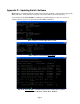
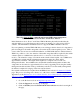
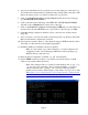
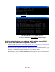
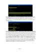
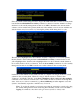
Table Of Contents
- Contents
- Glossary of Acronyms and Abbreviations
- 1.0 Purpose
- 2.0 Intended Audience
- 3.0 Objectives
- 4.0 Prerequisites
- 5.0 Skills
- 6.0 The HP ProCurve Threat Management Services zl Module
- 7.0 Common TMS Security Control Points
- 8.0 Deployment Considerations
- 9.0 Installation and Preparation of the TMS zl Module
- 10.0 Configuration of the TMS zl Module
- 11.0 Using multiple HP ProCurve Threat Management Services zl Modules
- Appendix A – Additional References
- Appendix B – Sample Company Information Assets Spreadsheet
- Sample “Information Assets” tab (See Embedded “Company Information Assets” Microsoft Excel 2003 spreadsheet)
- “Server Network Details” tab (See Embedded “Company Information Assets” Microsoft Excel 2003 spreadsheet)
- “TMS Zones” tab (See Embedded “Company Information Assets” Microsoft Excel 2003 spreadsheet)
- “Firewall Rules” tab (See Embedded “Company Information Assets” Microsoft Excel 2003 spreadsheet)
- /Sample “Company Information Assets” Microsoft Excel 2003 spreadsheet
- Appendix C – Information Gathering Tools
- Appendix D - Updating Switch Software
- Appendix E – Emergency Recovery Process
Page 11
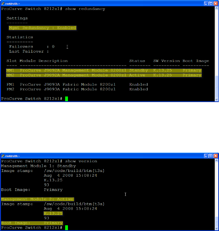
The first yellow highlighted line above shows redundancy is enabled. The second and third
yellow highlighted lines above show that the 8212 zl Switch used in this example does have a
second management module installed in Slot MM2 and it is currently in active mode.
The second step is to perform the show version CLI command and look for the value of the
default “Boot Image:”
The first yellow highlighted line above shows that the management module in Slot MM2 is the
active management module at this time. This information will become important to note as this
process will force switchovers between the two management modules in order to minimize the
traffic outage time caused by the switch software update. The second yellow highlighted line
above indicates that the switch is currently running on a K.13.25 software image. Based on the
previous output from the show modules CLI command, the K.13.25 software image doesn’t
recognize the HP ProCurve TMS zl Modules. The third yellow highlighted line above shows
that the management modules are currently configured to boot from their primary flash image.
The previous section showed how to download updated software images from the HP ProCurve
web site and securely transfer them to the switch. Here, in the output of the show flash
command, we see that K.13.51 is available in the secondary flash of the switch and that the
switch is currently configured to boot from its primary flash.