
TMS zl Module Planning and Implementation Guide 2009-08
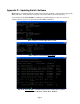
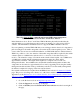
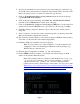
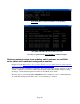
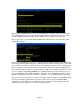
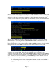
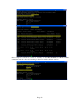
Table Of Contents
- Contents
- Glossary of Acronyms and Abbreviations
- 1.0 Purpose
- 2.0 Intended Audience
- 3.0 Objectives
- 4.0 Prerequisites
- 5.0 Skills
- 6.0 The HP ProCurve Threat Management Services zl Module
- 7.0 Common TMS Security Control Points
- 8.0 Deployment Considerations
- 9.0 Installation and Preparation of the TMS zl Module
- 10.0 Configuration of the TMS zl Module
- 11.0 Using multiple HP ProCurve Threat Management Services zl Modules
- Appendix A – Additional References
- Appendix B – Sample Company Information Assets Spreadsheet
- Sample “Information Assets” tab (See Embedded “Company Information Assets” Microsoft Excel 2003 spreadsheet)
- “Server Network Details” tab (See Embedded “Company Information Assets” Microsoft Excel 2003 spreadsheet)
- “TMS Zones” tab (See Embedded “Company Information Assets” Microsoft Excel 2003 spreadsheet)
- “Firewall Rules” tab (See Embedded “Company Information Assets” Microsoft Excel 2003 spreadsheet)
- /Sample “Company Information Assets” Microsoft Excel 2003 spreadsheet
- Appendix C – Information Gathering Tools
- Appendix D - Updating Switch Software
- Appendix E – Emergency Recovery Process
Page 15
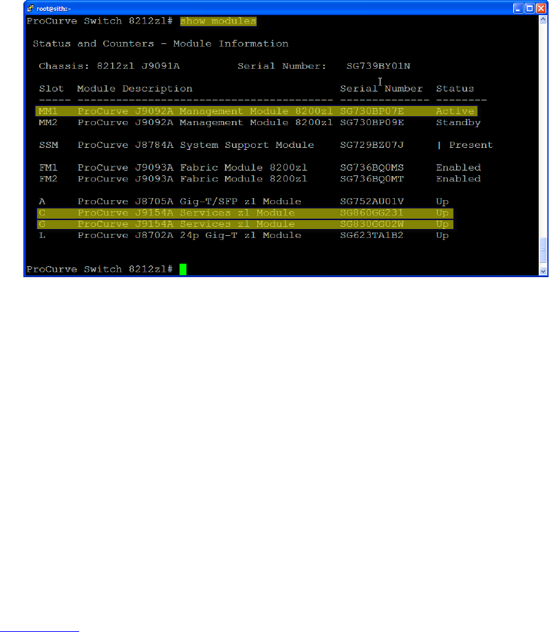
Issue the show modules command and note that it confirms the management module in slot
MM1 is the active one and that now the TMS zl Modules installed in slots C and G are
recognized as illustrated below.
Reversing the process to boot to the original software image can be accomplished by issuing the
boot set-default flash primary, boot standby and redundancy switchover commands.
Emergency Recovery Process
Although it is exceedingly rare, it has been observed that it is possible to get a switch into a
condition where it will not boot past the ROM monitor or continually reboot. This could be
through the combination of the erase flash command and incorrectly upgrading the switch
software in both the primary and secondary flash without first testing the new switch software in
one flash memory bank prior to upgrading the other. In this situation, connecting through the
serial console port of the switch will offer the option of entering the ROM monitor during the
boot process.
This capability can also be used to perform a backup of the management module compact flash
card prior to attempting an update by pulling it and accessing it from a PC. If there are
redundent management modules installed, this process could be done one module at a time to
limit the outage window.
See Appendix E for the steps involved in this process.