
TMS zl Module Planning and Implementation Guide 2009-08
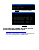
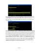
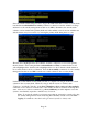
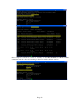
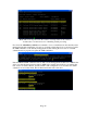
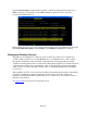
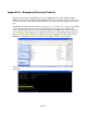
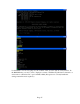
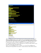
Table Of Contents
- Contents
- Glossary of Acronyms and Abbreviations
- 1.0 Purpose
- 2.0 Intended Audience
- 3.0 Objectives
- 4.0 Prerequisites
- 5.0 Skills
- 6.0 The HP ProCurve Threat Management Services zl Module
- 7.0 Common TMS Security Control Points
- 8.0 Deployment Considerations
- 9.0 Installation and Preparation of the TMS zl Module
- 10.0 Configuration of the TMS zl Module
- 11.0 Using multiple HP ProCurve Threat Management Services zl Modules
- Appendix A – Additional References
- Appendix B – Sample Company Information Assets Spreadsheet
- Sample “Information Assets” tab (See Embedded “Company Information Assets” Microsoft Excel 2003 spreadsheet)
- “Server Network Details” tab (See Embedded “Company Information Assets” Microsoft Excel 2003 spreadsheet)
- “TMS Zones” tab (See Embedded “Company Information Assets” Microsoft Excel 2003 spreadsheet)
- “Firewall Rules” tab (See Embedded “Company Information Assets” Microsoft Excel 2003 spreadsheet)
- /Sample “Company Information Assets” Microsoft Excel 2003 spreadsheet
- Appendix C – Information Gathering Tools
- Appendix D - Updating Switch Software
- Appendix E – Emergency Recovery Process
Page 19
loaded in the switch’s primary flash. In the next yellow highlighted line we see that the
configuration file that will be loaded when the switch is booted from the switch software in the
primary flash is the file “config1” found in the ‘cfg’ subdirectory. Finally, in the last yellow
highlighted line we see confirmation in the description that this block pertains to the primary
software image.
So, if we want to replace the primary switch software image because it has become non-
bootable, we would copy over a known good switch software image (e.g. “K_13_25.swi”) to the
compact flash card and name it “btm.swi”. This file operation is a matter of tens of seconds vs.
the tens of minutes it would take to accomplish the same thing via a serial connection and
XModem download.
In the third green highlighted section, “[secondary],” we see in the yellow highlighted line
immediately following it that the file “secondary.swi” contains the K.13.51 switch software
currently loaded in the switch’s secondary flash. Just like with the “[primary]” section
previously, we see in the next yellow highlighted line that the configuration file that will be
loaded when the switch is booted from the switch software in the secondary flash is the file
“config1” found in the ‘cfg’ subdirectory. Finally, similar to the “[primary]” section above we
see in the last yellow highlighted line confirmation that this block pertains to the secondary
software image.
If we want to replace the secondary switch software image because it has become non-bootable,
we would copy over a known good switch software image(e.g. “K_13_25.swi”) to the compact
flash card and name it “secondary.swi”.
Again, while not immediately relevant to the emergency recovery there is an item worth noting
in the fourth green highlighted section, “[monitor]”. In the yellow highlighted line we see
confirmation that this section and references to monitor refer to the Monitor ROM Console.
Finally, while also not immediately relevant to the emergency recovery there is an item worth
noting in the last green highlighted section, “[config]”. We see in the yellow highlighted line
that the next boot of the switch will take place in accordance with the default boot order
indicated previously in the “[boot]” section (monitor, primary, secondary).