
TMS zl Module Planning and Implementation Guide 2009-08

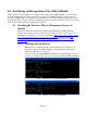
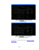
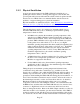
Table Of Contents
- Contents
- Glossary of Acronyms and Abbreviations
- 1.0 Purpose
- 2.0 Intended Audience
- 3.0 Objectives
- 4.0 Prerequisites
- 5.0 Skills
- 6.0 The HP ProCurve Threat Management Services zl Module
- 7.0 Common TMS Security Control Points
- 8.0 Deployment Considerations
- 9.0 Installation and Preparation of the TMS zl Module
- 10.0 Configuration of the TMS zl Module
- 11.0 Using multiple HP ProCurve Threat Management Services zl Modules
- Appendix A – Additional References
- Appendix B – Sample Company Information Assets Spreadsheet
- Sample “Information Assets” tab (See Embedded “Company Information Assets” Microsoft Excel 2003 spreadsheet)
- “Server Network Details” tab (See Embedded “Company Information Assets” Microsoft Excel 2003 spreadsheet)
- “TMS Zones” tab (See Embedded “Company Information Assets” Microsoft Excel 2003 spreadsheet)
- “Firewall Rules” tab (See Embedded “Company Information Assets” Microsoft Excel 2003 spreadsheet)
- /Sample “Company Information Assets” Microsoft Excel 2003 spreadsheet
- Appendix C – Information Gathering Tools
- Appendix D - Updating Switch Software
- Appendix E – Emergency Recovery Process

Page 47
9.1.2 Physical Installation
As previously demonstrated, if the TMS zl Module is installed prior to
updating the switch software to an image that supports it, the module will
power up but will be inaccessible until the switch software is updated and the
chassis rebooted. HP ProCurve recommends that the switch software be
updated to a supported image prior to physical installation.
Physical installation is detailed in Section 1 of the HP ProCurve Switch Threat
Management Services zl Module Installation and Getting Started Guide. An
abbreviated version is included here for convenience.
The following factors need to be considered to determine which slot(s) to
install the TMS zl Module(s) into to maintain proper maximum operating
temperature for the host switch:
• In 5400zl-series switches the maximum operating temperature of the
switch to host a TMS zl Module is impacted depending on the slot in
which it will be installed. Due to the cooling design of the 5400-series
products, TMS zl Modules can be supported in left-hand slots (when
looking at the front of the switch, i.e. A, C, E, etc.), at a higher
maximum operating temperature than when installed in right-hand slots
(when looking at the front of the switch, i.e. B, D, F, etc.). If all TMS
zl Modules are installed in left-hand slots, the switch’s maximum
operating temperature is 50° C / 122° F. If any TMS zl Modules are
installed in right-hand slots, the switch’s maximum operating
temperature is 40° C / 104° F.
• A 5406zl chassis has only three left hand slots. In order to stay within
the 50°C / 122° F temperature specification, only three TMS zl
Modules are supported in this chassis.
• For the 8200zl switch series, the maximum operating temperature
specification is 40°C / 104° F up to the maximum supported 4 TMS zl
Modules in any slot combination.
Taking the previous maximum operating temperature information into
consideration along with other considerations (e.g. available slots in the
chassis) choose which slot into which the TMS zl Module will be installed. As
with any exposed electronics, be sure to take proper electrostatic discharge
precautions while handling the TMS zl Module during physical installation. A
Torx T-10 or flat-bladed screwdriver may be needed to unscrew the screws in
the blank adapter currently over the slot where the module is to be installed.
Handle the module by its metal faceplate, taking care not to touch the
components on the board or the backplane contacts. Also remember that, like
all HP ProCurve switch modules, the TMS zl Module uses low-insertion-force
connectors so high-insertion forces are unnecessary and if used, are more
likely to damage the module. Remove the blank adapter currently over the slot
where the module is to be installed, open the extractor handles on the TMS zl
module, insert the module with the board edges aligned with the guides in the
slot, slide it into the slot until it is fully inserted and the contacts have begun to