
TMS zl Module Planning and Implementation Guide 2009-08
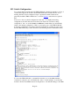
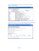
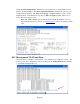
Table Of Contents
- Contents
- Glossary of Acronyms and Abbreviations
- 1.0 Purpose
- 2.0 Intended Audience
- 3.0 Objectives
- 4.0 Prerequisites
- 5.0 Skills
- 6.0 The HP ProCurve Threat Management Services zl Module
- 7.0 Common TMS Security Control Points
- 8.0 Deployment Considerations
- 9.0 Installation and Preparation of the TMS zl Module
- 10.0 Configuration of the TMS zl Module
- 11.0 Using multiple HP ProCurve Threat Management Services zl Modules
- Appendix A – Additional References
- Appendix B – Sample Company Information Assets Spreadsheet
- Sample “Information Assets” tab (See Embedded “Company Information Assets” Microsoft Excel 2003 spreadsheet)
- “Server Network Details” tab (See Embedded “Company Information Assets” Microsoft Excel 2003 spreadsheet)
- “TMS Zones” tab (See Embedded “Company Information Assets” Microsoft Excel 2003 spreadsheet)
- “Firewall Rules” tab (See Embedded “Company Information Assets” Microsoft Excel 2003 spreadsheet)
- /Sample “Company Information Assets” Microsoft Excel 2003 spreadsheet
- Appendix C – Information Gathering Tools
- Appendix D - Updating Switch Software
- Appendix E – Emergency Recovery Process
Page 63
10.2 Switch Configuration
Let’s assume that the switch where the TMS zl Module is installed is running a version of
software that supports the module, and the TMS zl Module is installed in Slot “D”, is
running, but has not been configured. Steps to update the switch software and to
physically install the TMS zl Module are covered in Section 9 and will not be repeated
here.
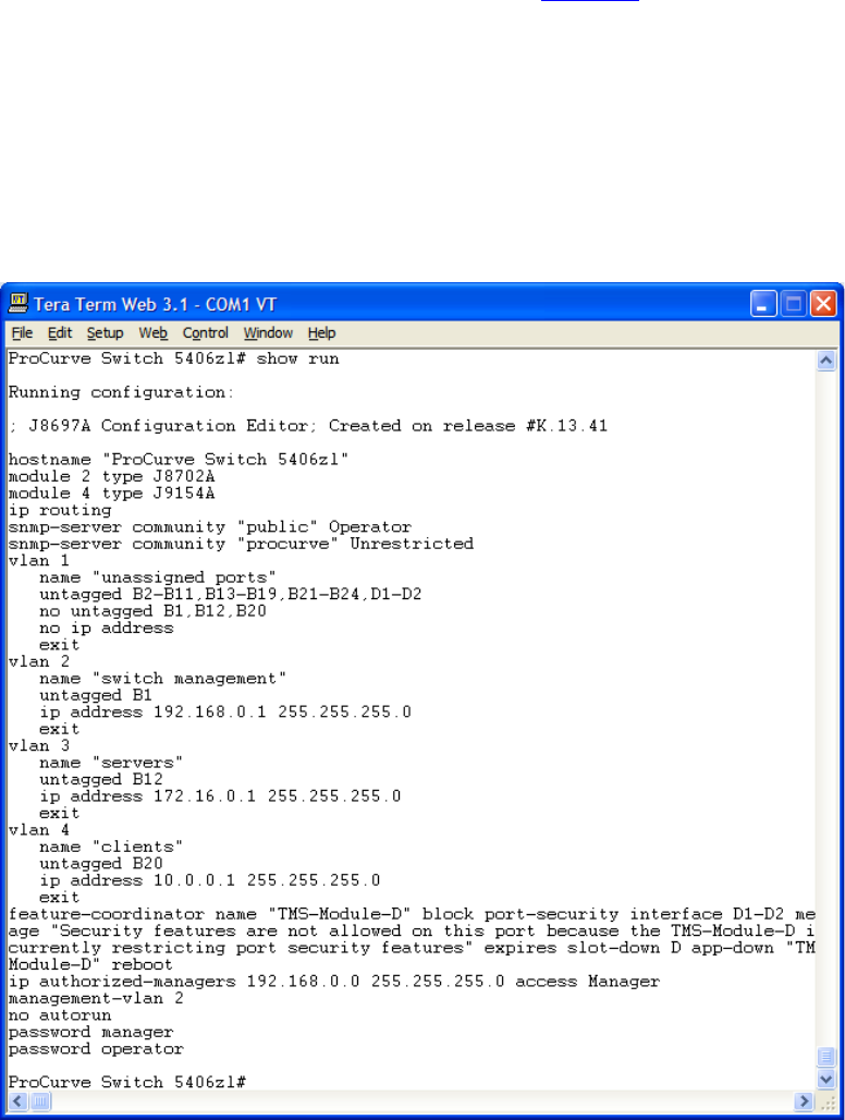
Now let’s look at our switch configuration in this state. To simplify the running-
configuration, the ACLs that were in use have been deleted as well as the routing
configuration. Also, we see the feature-coordinator command that was automatically
added to the running-configuration. This is to protect the ports on the TMS zl Module
from being configured in a way that would prevent them from operating properly. Note
that the TMS zl Module ports D1 and D2 are automatically placed in the default VLAN.
To access the TMS zl Module’s command line interface, we use the show services
command to verify the “slot” and identify the “index”. In this example, we see that the
module is in Slot D and TMS software is using Index 2. We will then change to the TMS