Getting Started Guide ProCurve Wireless EDGE Services xl Modules www.procurve.
© Copyright 2007 Hewlett-Packard Development Company, L.P. The information contained herein is subject to change without notice. Publication Number Disclaimer The only warranties for HP products and services are set forth in the express warranty statements accompanying such products and services. Nothing herein should be construed as constituting an additional warranty. HP shall not be liable for technical or editorial errors or omissions contained herein.
Contents Introduction . . . . . . . . . . . . . . . . . . . . . . . . . . . . . . . . . . . . . . . . . . . . . . . . . . . . . . 1 Minimum Software Version . . . . . . . . . . . . . . . . . . . . . . . . . . . . . . . . . . . . . 2 General Operation . . . . . . . . . . . . . . . . . . . . . . . . . . . . . . . . . . . . . . . . . . . . . 2 Radio Port Adoption . . . . . . . . . . . . . . . . . . . . . . . . . . . . . . . . . . . . . . . . 2 Building a Wireless LAN System . . . . . . . . . . . . . . . . . .
Restore Config Files to Factory Defaults . . . . . . . . . . . . . . . . . . . . . . . . . . . . . . 31 Reboot or Shutdown . . . . . . . . . . . . . . . . . . . . . . . . . . . . . . . . . . . . . . . . . . . . . . 32 Uplink/Downlink Port MAC Addresses . . . . . . . . . . . . . . . . . . . . . . . . . . . . . . . 32 Related Publications . . . . . . . . . . . . . . . . . . . . . . . . . . . . . . . . . . . . . . . . . . . . . .
Introduction Introduction This Getting Started Guide supports the following ProCurve xl Modules: ■ ProCurve Wireless Edge Services xl Module (J9001A). ■ ProCurve Redundant Wireless Edge Services xl Module (J9003A). The ProCurve Wireless Edge Services xl Module (Module) enables a ProCurve Switch 5300xl Series to operate with ProCurve Radio Ports as a centrallyadministered wireless LAN (WLAN) system.
Introduction Minimum Software Version This document is included with ProCurve Wireless Edge Services xl Modules (J90001A), and Redundant Wireless Services xl Modules (J9003A), with Module software version WS.02.07 (or later). ProCurve 5300xl series switches operating with software version E.10.30 may be used. However, version E.10.60 or later is recommended for access to new features.
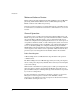
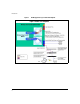
Introduction Building a Wireless LAN System A Wireless LAN system contains a wireless services-enabled switch with VLANs, radio ports, and WLANs. Wireless Services-Enabled Switch A wireless services-enabled switch is a 5300xl series switch with a Wireless Edge Services xl Module installed. By connecting a number of distributed ProCurve radio ports (RPs), the desired wireless LAN coverage can be provided. The connected radio ports are centrally managed through the Module.
Introduction ■ Radio Port VLAN (For Layer 2 Adoption only): A VLAN that carries wireless traffic as well as management, control and status information between the Module and radio ports when they are both on the same Layer 2 domain (subnet). The VLAN ID is 2100 by default. • The Module’s Downlink port is a tagged member of this VLAN. • Each switch port that directly connects a radio port must be an untagged member of this VLAN. Auto-VLAN: With software version E.10.
Introduction Note Setting the VLANs in the Module does not set the VLANs in the 5300xl switch. Normally, the administrator will set the VLANs in the 5300xl Switch first, then set the VLANs in the Module to correspond with the switch VLAN settings. For Layer 2 radio port adoption, routing may not be used in the communications path between the wireless services-enabled 5300xl switch and the radio port.
Introduction Figure 1.
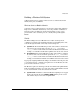
Introduction Figure 2.
Introduction Radio Ports ProCurve Radio Ports provide the radio-based infrastructure to support wireless client connectivity and RF environment sensing and reporting. The table below summarizes their features. RADIO PORTS A radio port has 1 or 2 radios. ProCurve radio ports are: • ProCurve Radio Port 210 (J9004A) - Single-radio (802.11b/g) radio port; embedded 2.
Introduction WLANs RADIUS Authentication • 802.1X EAP • Web Auth (open) for hotspots • RADIUS-based ACLs using ProCurve Identity Driven Management Encryption • WEP • WPA/WPA2-TKiP • WPA2-AES • WPA2/AES-TKIP (802.11i Mixed Mode) WLAN Configuration Modes • Up to 16 WLANs can be configured per Module in the Normal Mode (the default). • Up to 32 WLANS can be configured per Module in the Advanced Configuration Mode.
Introduction Managing a Wireless LAN System An administrator uses a wireless services-enabled Switch 5300xl to manage radio ports in a Wireless LAN System from one centralized interface. This provides the following: ■ System-wide configuration, enabling coordinated configuration of WLAN policies, and security across multiple radio devices. ■ System-wide view, providing security and unapproved-AP detection.
Introduction ■ A Module by default does not participate in any Redundancy Group and is standalone. For a set of Wireless Edge Services xl Modules to become a Redundancy Group, the administrator must configure each of them to know about the other. Multiple groups may be formed and operated independently. Each group is identified by a unique Group ID. ■ A Redundancy Group consists of a primary and one or more redundant Modules, up to a total of 12 Modules.
Getting Started Getting Started Use the following steps to install the equipment and build three configuration examples. 1. Review the equipment list, connect the equipment, verify the ProCurve 5300xl Switch software. 2. Boot up the system. 3. Determine Module IP address. 4. Launch Module’s Web browser interface. 5. Set up Country Code and other wireless network administrative data. 6. Verify Radio Port adoption. 7. Configure the Module. Three configuration examples are illustrated.
Getting Started ■ ■ ProCurve Radio Port 220 (J9005A) with external antennas. ProCurve 2600-PWR or other switch providing PoE (802.3af-compliant) power. A wireless services-enabled Switch 5300xl has the following recommended minimum requirements: • ProCurve Switch 5300xl must be connected to a network with DHCP services enabled, or have a local DHCP service to provide IP addresses. • ProCurve Switch 5300xl must have at least one module for connecting to the wired network.
Getting Started Verify 5300xl Switch Software Start a console session. The following CLI commands show the switch software version. The ProCurve 5300xl Switch software must be version E.10.30 or later (E.10.60 or later is recommended). ProCurve# show version Image stamp: /sw/code/build/alpmo(lor) Jan 23 2007 15:41:58 E.10.30 255 Boot Image: Primary ProCurve# Step 2 - Boot up the system. 1. 2.
Getting Started 3. • After the amber light blinks for approximately 5 seconds, both LEDs solidly light for about 5 seconds. • Then, both the LEDs blink about once every 5 seconds, indicating that the Radio Port is adopted and ready for use. For more details on the LEDs activity of the radio ports, please refer to the Radio Port Install Guides for the respective models (210, 220, and 230). Step 3 - Determine Module IP address.
Getting Started The CLI command prompt, ’ProCurve#, is at the Switch 5300xl Manager context level. Type the following CLI commands to determine the Module IP address for a Module in the ’B’ slot of the 5300 xl Switch. Hence, for this setup the Module IP address is 10.168.2.5. ProCurve# configure ProCurve(config)# wireless-services b ProCurve(wireless-services-B)#show ip interface Interface IP-Address Status vlan1 10.168.2.5(DHCP) up ProCurve(wireless-services-B)# 2.
Getting Started 4. On the Wireless Edge Services Module login page, enter the default User ID (manager)and Password (procurve), and click Login. The Device Information Web browser screen for the Module appears, as shown below. It is recommended the administrator immediately change the Password (see “Change Password” below).
Getting Started Note the message in the upper right corner of the screen, Country Code not set. Use Network setup page to set Country Code. To set the country code, see “Step 5 - Set up Country Code and other wireless network administrative data.” on page 21. Note This device requires the administrator to select the appropriate Country Code during the initial setup of the Module.
Getting Started Chassis Information: • Name - The Name is the chassis or switch name in which the Wireless Edge Services Module is installed. Chassis names are used to differentiate the switch from the system name that could possibly be used on more than one switch. The Chassis Name (as well as all the information in the Chassis Information field) is retrieved from the switch. • Management IP - The IP Address defined for the Management IP unique to this chassis.
Getting Started Change Password It is recommended the administrator change the default Password. 20 1. Select Management > Web-Users > Local Users. On this screen highlight manager and select Edit. 2. Enter a new password, using the Password and the Confirm Password fields. Select OK. The new password is assigned, and will be required the next time you log on.
Getting Started Step 5 - Set up Country Code and other wireless network administrative data. In this step, the Module is set up with the Country Code and other administrative data. 1. From the Navigation Pane, select Network Setup 2. Using the Country list box, select the appropriate Country Code. 3. Enter data for the System Name, Location, and Contact if desired. 4. Select Apply to save the settings for this session. 5.
Getting Started Step 6 - Verify Radio Port adoption. To verify that the radio ports have been adopted by the Module, select Device Information > Radio Adoption Statistics. If some of the radio ports are not found on this screen, check the status of the LEDs on the missing radio ports. 22 • If both the LEDs blink about once every 5 seconds, the Radio Port is adopted and ready for use. • If the amber light is continuously blinking, with the green light out. the radio port is in the unadopted mode.
Getting Started Step 7 - Configure the Module You must configure the Module to assign user-specified WLANs to Radio Ports. This section provides configuration examples using Normal Mode, which is suitable in most cases. You simply configure and enable WLANs, and adopted RPs begin to support those WLANs automatically. In Normal Mode configuration, the Module and RPs are limited to 16 WLANs. Advanced Mode is performed manually, to control WLAN assignment to Radio Ports or to extend the number of WLANs.
Getting Started 2. Click and highlight Index 1. Select Edit or double-click on the Index line and an Edit screen appears. WLAN1 is specified in the categories of Configuration, Advanced, Authentication, and Encryption. For this example, enter the following settings: • SSID = Faculty1 • Description = Faculty • VLAN ID = 1 • Encryption = WEP 64-bits (Use the Config button to configure encryption settings as desired.) 3.
Getting Started In this example, all of the radios are assigned to the WLAN with the Faculty1 SSID, and operate on BSS-ID 1. 6. The Module, wireless services-enabled Switch, and the radio ports are now operational in Normal Mode. Using your wireless-enabled laptop PC, confirm that the wireless network with SSID (network name) “Faculty1” is available. Configuration 2 - Normal Mode with five WLANs and two radio ports.
Getting Started 2. Note 26 To review the BSSID and SSID assignments, select Network Setup > Radio > WLAN Assignments. On the right side of the screen, the 5 WLAN(SSIDs) are noted and their assignments to the 4 BSSIDs. Note that BSSID1 is assigned to Faculty1 and Math5, which correspond to SSID1 and SSID5. SSID Math5 is shared on BSSID 1, but is not beaconed by the Radio Port. Only SSID Faculty1 is beaconed on BSS-ID 1. RP radios send beacon frames to announce the WLANs that they support.
Getting Started Configuration 3 - Adding redundancy. In this example,the following modules will be set up in a Redundancy Group. ■ ProCurve Wireless Edge Service xl Module (J9001A). ■ ProCurve Redundant Wireless Services xl Module (J9003A). Note: For the optimal redundancy and protection, the preferred setup is for the J9001A and J9003A to be installed in different chassis. However, these modules may be installed in the same chassis. 1.
Getting Started 3. The next step is to add the IP address of the redundant member. Select the screen Network Setup > Redundancy Group> Member. Select Add and a pop-up screen appears. Enter the IP address of the new Group member (J9003A). Select OK to return to the main screen. 4. Next, repeat these steps with the J9003A module, using its IP address for the Interface IP, and the IP address of the J9001A module as the Member.
Loading New Module Software Loading New Module Software Note When updating software, read the release notes provided with the software update files for special instructions. For example, updating software between WS.01.11 and WS.02.07 (or later) may require you to clear your browser and Java cache before you can log in after a reboot. To load new Module software, follow these steps: 1. Select Management > System Maint. - Software.
Loading New Module Software 3. Select the Upgrade Software button, and the Upgrade Screen appears. Enter the appropriate information: – Enter the update filename (for example, "WS.02.07.img"). The filename is case-sensitive. – Select TFTP or FTP as appropriate – Enter the IP address of the TFTP or FTP server (for example, 192.168.2.3). – For an FTP server, enter the User ID and Password for server access. – Enter the path to the file on that server, or "/" if it is located in the TFTP or FTP server root.
Restore Config Files to Factory Defaults Restore Config Files to Factory Defaults To restore the configuration files to factory default settings, select Management > System Maint. - Config Files. Highlight the desired configuration file, the select Restore Defaults. When prompted, select Yes.
Reboot or Shutdown Reboot or Shutdown Use the Management screen to reboot or shutdown the Wireless Edge Services Module. ■ Reload - Click Reload to reboot the Wireless Services Module. The following warning screen appears: Select either Primary or Secondary to select the software version to boot from, then click Reload to proceed with rebooting the module. ■ Shutdown - Click Shutdown to halt (stop) the Wireless Services Module.
Related Publications Use the ProCurve 5300xl switch publications to install the 5300xl switch and to physically install the ProCurve Module and the ProCurve Redundant Wireless Services xl Module. These publications provide the command references for the 5300xl Switch that are necessary to access the Module. For radio port installation instructions, see the Installation and Getting Started Guide supplied with the radio ports.
Related Publications 34
Technical information in this document is subject to change without notice. © Copyright 2007 Hewlett-Packard Development Company, L.P. Reproduction, adaptation, or translation without prior written permission is prohibited except as allowed under the copyright laws.