
WESM xl Getting Started Guide 2007-08

3
Introduction
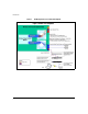
Building a Wireless LAN System
A Wireless LAN system contains a wireless services-enabled switch with
VLANs, radio ports, and WLANs.
Wireless Services-Enabled Switch
A wireless services-enabled switch is a 5300xl series switch with a Wireless
Edge Services xl Module installed. By connecting a number of distributed
ProCurve radio ports (RPs), the desired wireless LAN coverage can be
provided. The connected radio ports are centrally managed through the
Module.
VLANs
The Wireless Edge Services xl Module has no visible external ports. It
communicates with the wired (uplink) and wireless (downlink) sides of the
network through the VLAN connectivity of its internal ports:
■ Uplink Port: The internal Module port that carries traffic to and from the
wired side of the network. The port name is <slot_ID>UP, where
<slot_ID> is the 5300xl switch slot in which the Module is installed. For
example, CUP identifies the Module’s Uplink Port in slot C of the switch.
■ Downlink Port: The internal Module port that carries traffic to and from
the wireless side of the network. The port name is <slot_ID>DP, where
<slot_ID> is the 5300xl switch slot in which the Module is installed. For
example, CDP identifies the Module’s Downlink Port in slot C of the switch
By properly assigning VLAN memberships to the Module’s internal ports and
to 5300xl switch ports, communication paths between the Module, the radio
ports, and the network are created.
The Module requires two VLAN types: Radio Port VLANs and Uplink VLANs.
Radio Port VLANs send and receive radio port traffic. Uplink VLANs send and
receive network traffic on the wired side of the network.
■ Uplink VLAN: A VLAN that contains the Module’s Uplink port as a tagged
member. By default, this is the DEFAULT_VLAN (VLAN 1) on the 5300xl
switch. There may be more than on uplink VLAN.