
Wireless/Redundant Edge Services xl Module Management and Configuration Guide WS.01.03 or greater


1-11
Introduction
ProCurve Wireless Edge Services xl Module
4. The module forwards the traffic through the uplink port.
If you have not enabled the uplink port to carry tagged traffic for the uplink
VLAN, then the module drops the traffic.
5. The wireless services-enabled switch forwards the traffic toward its
destination.
Much depends on the way in which the module tags traffic for various VLANs.
For example, the module receives a VLAN assignment for a particular user
from a RADIUS server. It then tags all traffic from that user for that VLAN as
it forwards it to the wireless services-enabled switch. The switch limits the
user’s network access accordingly.
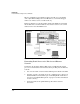
The module follows a similar process to forward traffic from the Ethernet
network to wireless stations:
1. It receives the traffic on its uplink port in an uplink VLAN.
2. It applies controls to the traffic, if any are configured.
3. It tags the traffic for the Radio Port VLAN specified for the radio to which
the destination station has associated.
4. It forwards the traffic toward its destination on its downlink port.
Layer 2 Versus Layer 3 Operation
The ProCurve Wireless Edge Services xl Module’s downlink port and associ-
ated RPs are Layer 2 devices. The module is not designed to route traffic
between wireless stations and RPs, but rather to control that traffic before
forwarding it into an Ethernet network, as described above.
This functionality suits wireless networks, in which the bulk of traffic is
destined for servers in the Ethernet network or a router that connects to the
Internet. The same devices that route traffic from traditional users can route
traffic from the wireless stations.
As Layer 2 devices, RPs do not have IP addresses; the module manages all
communications with them. Similarly, the module’s downlink port does not
have an IP address.
The Wireless Edge Services xl Module itself, as well as its uplink port, operate
at Layer 3.