
Wireless/Redundant Edge Services xl Module Management and Configuration Guide WS.01.03 or greater


1-12
Introduction
ProCurve Wireless Edge Services xl Module
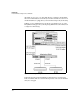
The module’s uplink port can acquire an IP address, which you can use to:
■ access the module’s management interface
■ test connectivity
■ configure the module to forward authentication information to a RADIUS
server
■ configure the module to communicate with another member of a redun-
dancy group
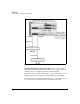
As described in “Communicating with the Ethernet Network: Uplink VLANs”
on page 1-9, the uplink port can carry traffic on multiple VLANs. You can assign
the uplink port an IP address on each of these VLANs.
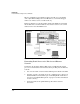
While typically the module does not route traffic between uplink VLANs, it
can do so. Thus, if for whatever reason your wireless services enabled-switch
cannot route traffic, the module itself can implement basic routing at the edge.
(You should not enable routing on the module if the switch in which it is
installed also routes traffic.)
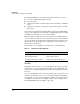
Refer to Table 1-1 for a summary of the functions on each internal port.
Table 1-1. Layer 2 Versus Layer 3 Operation
WLANs
In this guide, the term wireless network will describe all the devices (such as
stations, RPs, access points [APs], Wireless Edge Services xl Modules, and
wireless services-enabled switches) involved in your organization’s wireless
functions.
A wireless LAN (WLAN), on the other hand, will refer more precisely to a set
of wireless stations that connect to one or more RPs using the same SSID, or
network name. A more technical definition of a WLAN, as well as its relation
to an SSID, an extended service set (ESS), a basic service set (BSS), and a
basic SSID (BSSID), is given in “ESS” on page 1-34.
Downlink Port Uplink Port
No IP address IP address on any or all uplink VLANs
Traffic forwarded at Layer 2 Traffic forwarded at Layer 2
No routing between Radio Port VLANs Routing between uplink VLANs (optional)