HP ProLiant ML350p Gen8 Server User Guide Abstract This document is for the person who installs, administers, and troubleshoots servers and storage systems. HP assumes you are qualified in the servicing of computer equipment and trained in recognizing hazards in products with hazardous energy levels.
© Copyright 2012 Hewlett-Packard Development Company, L.P. The information contained herein is subject to change without notice. The only warranties for HP products and services are set forth in the express warranty statements accompanying such products and services. Nothing herein should be construed as constituting an additional warranty. HP shall not be liable for technical or editorial errors or omissions contained herein. Microsoft and Windows are U.S. registered trademarks of Microsoft Corporation.
Contents Component identification ............................................................................................................... 7 Front panel components ................................................................................................................................ 7 Front panel LEDs and buttons ......................................................................................................................... 8 Rear panel components ...................................
Setting up a tower server ............................................................................................................................ 35 Installing the server into the rack .................................................................................................................. 36 Powering up and configuring the server........................................................................................................ 37 Installing the operating system ..........................
HP Smart Update Manager ............................................................................................................... 90 HP ROM-Based Setup Utility ........................................................................................................................ 91 Using RBSU ..................................................................................................................................... 91 Auto-configuration process ...............................................
Specifications ........................................................................................................................... 109 Environmental specifications ...................................................................................................................... 109 Server specifications ................................................................................................................................. 109 Power supply specifications .................................
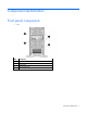
Component identification Front panel components • SFF Item Description 1 Media/Drive cage bay 2 SAS/SATA drives (8) 3 Optical drive 4 USB connectors (4) Component identification 7
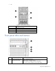
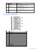
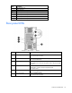
• LFF Item Description 1 Media/Drive cage bay 2 SAS/SATA drive (6) 3 Optical drive 4 USB connectors (4) Front panel LEDs and buttons Item Description Status 1 Power On/Standby button and system power LED Green = Normal (system on) Flashing green = waiting for power Amber = System in standby, but power still applied Off = Power cord not attached or power supply failure Component identification 8
Item Description Status 2 NIC statusLED Green = Network link Flashing green = Network link and activity Off = No link to network 3 Health LED Green = Normal (system on) Flashing amber = System health is degraded Flashing red = System health is critical Off = Normal (system off) 4 UID LED Blue = Activated Flashing blue = System is being managed remotely Off = Deactivated Rear panel components Item Description 1 Power supply 4 2 Power supply 3 3 Power supply 2 4 Power supply 1 5 PCIe s
Item Description 16 USB connectors (4) 17 Video connector 18 PCIe slot 5 (Processor 2) 19 PCIe slot 6 (Processor 2) 20 PCIe slot 7 (Processor 2) 21 PCIe slot 8 (Processor 2) 22 PCIe slot 9 (Processor 2) Rear panel LEDs Item Description Status 1 NIC activity LED Green = Linked to network Off = No network connection 2 NIC link LED Green or flashing green = Network activity Off = No network activity 3 Power supply LED Green = System has AC power and is powered up Off = System has no
System board components Item Description 1 Slot 1 PCIe3 x16 (8, 4, 1) 2 Slot 2 PCIe3 x8 (4, 1) 3 Slot 3 PCIe3 x16 (16, 8, 4, 1) 4 Slot 4 PCIe3 x8 (4, 1) 5 Processor 1 DIMM slots 6 Smart Array P420i memory cache module 7 Mini-SAS connectors (2) 8 Processor 2 DIMM slots 9 Processor socket 2 10 SD card slot 11 Front panel connectors (2) 12 Fan cage connector 13 Internal USB tape connector 14 Discovery service cable connector 15 System battery 16 SATA connectors 17 Internal U
System maintenance switch The system maintenance switch (SW1) is a ten-position switch that is used for system configuration. Position Description Function S1 iLO security Off = iLO security enabled. On = iLO security disabled. S2 Configuration lock Off = Able to change system configuration. On = System configuration locked.
DIMM slots DIMM slots are numbered sequentially (1 through 12) for each processor. The supported AMP modes use the letter assignments for population guidelines. NOTE: For proper orientation, the arrow indicates the front of the server. Systems Insight Display LEDs The HP Systems Insight Display LEDs represent the system board layout.
Item Description Status 1 Power cap To determine Power cap status, see "Systems Insight Display LED combinations (on page 14)." 2 AMP Status Green = AMP mode enabled Amber = Failover Off = AMP mode disabled 3 DIMM LEDs Amber = DIMM error Off = Normal All other LEDs Amber = Failure Off = Normal IMPORTANT: If more than one DIMM slot LED is illuminated, further troubleshooting is required. Test each bank of DIMMs by removing all other DIMMs.
Systems Insight Display Health LED LED and color Power supply (amber) Amber System power LED Status Green • • • • Redundant power supply is installed and only one power supply is functional. AC power cord is not plugged into redundant power supply. Redundant power supply fault Power supply mismatch at POST or through hot-plug addition.
• LFF drives Drive LED definitions Item LED Status Definition 1 Locate Solid blue The drive is being identified by a host application. Flashing blue The drive carrier firmware is being updated or requires an update. Rotating green Drive activity Off No drive activity Solid white Do not remove the drive. Removing the drive causes one or more of the logical drives to fail. Off Removing the drive does not cause a logical drive to fail.
Item LED Status Definition Off The drive is not configured by a RAID controller. Fans The server supports redundant fans to provide proper airflow to the system when a primary fan fails. For more information, see "Redundant fan guidelines (on page 69)." IMPORTANT: Fan louvers must be present for the redundant configuration. Without the louvers, all four fans are nonredundant.
FBWC module LEDs (P222, P420, P420i, P421) The FBWC module has three single-color LEDs (one amber and two green). The LEDs are duplicated on the reverse side of the cache module to facilitate status viewing. 1 - Amber 2 - Green 3 - Green Interpretation Off Off Off The cache module is not powered. Off Flashing 0.5 Hz Flashing 0.5 Hz The cache microcontroller is executing from within its boot loader and receiving new flash code from the host controller.
RPS riser board connectors Item Connector Description 1 J7 Graphic card power connector 2 J9 Drive backplane bay 1/optical drive power connector 3 J5 Drive backplane bay 2 power connector 4 J6 Drive backplane bay 3 power connector 5 J8 Graphic card power connector Component identification 19
Operations Power down the server Before powering down the server for any upgrade or maintenance procedures, perform a backup of critical server data and programs. IMPORTANT: When the server is in standby mode, auxiliary power is still being provided to the system. To power down the server, use one of the following methods: • Press and release the Power On/Standby button. This method initiates a controlled shutdown of applications and the OS before the server enters standby mode.
1. Using the key provided with the server, unlock the bezel with a clockwise turn. 2. Remove the tower bezel.
Remove the security bezel Unlock the security bezel, press the latch on the security bezel, and then remove the security bezel. Install the security bezel Install the security bezel into the chassis, and then lock the security bezel with the key. Remove the rack bezel 1. If installed, remove the security bezel (on page 22). 2. Press the Power On/Standby button. The server powers down and enters standby mode. The system power LED changes from green to amber. Power is still applied to the server.
3. Remove all power: a. Disconnect each power cord from the power source. b. Disconnect each power cord from the server. 4. Extend the server from the rack (on page 25). 5. Remove the access panel (on page 24). 6. Loosen the thumbscrews. 7. Remove the rack bezel. Install the rack bezel 1. Install the rack bezel. 2. Tighten the thumbscrews. 3. Install the access panel (on page 24).
4. Slide the server back into the rack. Remove the access panel WARNING: To reduce the risk of personal injury from hot surfaces, allow the drives and the internal system components to cool before touching them. CAUTION: Do not operate the server for long periods with the access panel open or removed. Operating the server in this manner results in improper airflow and improper cooling that can lead to thermal damage. To remove the component: 1.
o For rack models, if removed, install the security bezel (on page 22). Extend the server from the rack IMPORTANT: If the server is installed in a telco rack, remove the server from the rack to access internal components. 1. Pull down the quick release levers on each side of the server. 2. Extend the server from the rack. WARNING: To reduce the risk of personal injury or equipment damage, be sure that the rack is adequately stabilized before extending a component from the rack.
4. Do one of the following: o For tower models, place the server on a flat, level surface with the access panel facing up. o For rack models, extend the server from the rack (on page 25). 5. Remove the access panel (on page 24). 6. Remove the air baffle (on page 25). Remove the fan CAUTION: To prevent improper cooling and thermal damage, do not operate the server unless all bays are populated with either a component or a blank. To remove the component: 1.
6. Remove the fan. Remove the fan cage IMPORTANT: When installing or replacing server components, one or more fans might need to be removed. To prevent an orderly or immediate server shutdown, HP highly recommends powering down the server during these procedures. To determine if powering down is required, see the specific procedure. To remove the component: 1. Do one of the following: o For tower models, open and remove the bezel ("Remove the tower bezel" on page 20).
7. Remove the fan cage (on page 27). Remove the FBWC capacitor pack CAUTION: To prevent a server malfunction or damage to the equipment, do not add or remove the capacitor pack while an array capacity expansion, RAID level migration, or stripe size migration is in progress. CAUTION: After the server is powered down, wait 15 seconds and then check the amber LED before unplugging the cable from the cache module. If the amber LED blinks after 15 seconds, do not remove the cable from the cache module.
9. Remove the capacitor pack. Remove the DVD drive The server supports both DVD-ROM and DVD-RW drives. 1. Do one of the following: o For tower models, open and remove the bezel ("Remove the tower bezel" on page 20). o For rack models, if installed, remove the security bezel (on page 22). 2. Power down the server (on page 20). 3. Remove all power: a. Disconnect each power cord from the power source. b. Disconnect each power cord from the server. 4. For tower models, do the following: a.
8. Remove the DVD-ROM drive. Remove the component drive cage blank 1. Do one of the following: o For tower models, open and remove the bezel ("Remove the tower bezel" on page 20). o For rack models, do the following: a. If installed, remove the security bezel (on page 22). b. Remove the access panel. ("Remove the access panel" on page 24) c. 2. Release thumbscrews and remove the rack bezel. ("Remove the rack bezel" on page 22) Remove the component drive cage blank.
Setup Optional installation services Delivered by experienced, certified engineers, HP Care Pack services help you keep your servers up and running with support packages tailored specifically for HP ProLiant systems. HP Care Packs let you integrate both hardware and software support into a single package. A number of service level options are available to meet your needs.
Space and airflow requirements Tower server In a tower configuration, leave at least a 7.6-cm (3-in) clearance space at the front and back of the server for proper ventilation. Rack server To allow for servicing and adequate airflow, observe the following space and airflow requirements when deciding where to install a rack: • Leave a minimum clearance of 63.5 cm (25 in) in front of the rack. • Leave a minimum clearance of 76.2 cm (30 in) behind the rack. • Leave a minimum clearance of 121.
CAUTION: To reduce the risk of damage to the equipment when installing third-party options: • Do not permit optional equipment to impede airflow around the server or to increase the internal rack temperature beyond the maximum allowable limits. • Do not exceed the manufacturer’s TMRA. Power requirements Installation of this equipment must comply with local and regional electrical regulations governing the installation of information technology equipment by licensed electricians.
Rack warnings WARNING: To reduce the risk of personal injury or damage to the equipment, be sure that: • • • • • The leveling jacks are extended to the floor. The full weight of the rack rests on the leveling jacks. The stabilizing feet are attached to the rack if it is a single-rack installation. The racks are coupled together in multiple-rack installations. Only one component is extended at a time. A rack may become unstable if more than one component is extended for any reason.
CAUTION: Do not operate the server for long periods with the access panel open or removed. Operating the server in this manner results in improper airflow and improper cooling that can lead to thermal damage. Identifying tower server shipping carton contents Unpack the server shipping carton and locate the materials and documentation necessary for installing the server.
1. Lay the server on the side, and then install the feet. 2. Return the server to an upright position. 3. Connect peripheral devices to the server ("Rear panel components" on page 9). WARNING: To reduce the risk of electric shock, fire, or damage to the equipment, do not plug telephone or telecommunications connectors into RJ-45 connectors. 4. Connect the power cord to the rear of the server. 5. Connect the power cord to the AC power source.
WARNING: This server is very heavy. To reduce the risk of personal injury or damage to the equipment: • Observe local occupational health and safety requirements and guidelines for manual material handling. • Get help to lift and stabilize the product during installation or removal, especially when the product is not fastened to the rails. When the server weighs more than 22.5 kg (50 lb), at least two people must lift the server into the rack together.
To install an operating system on the server with Intelligent Provisioning (local or remote): a. Connect the Ethernet cable, and then power on the server. b. During server POST, press the F10 key. c. Complete the initial Preferences and Registration portion of Intelligent Provisioning (on page 88). d. At the 1 Start screen, click the Configure and Install button. e. To finish the installation, follow the on-screen prompts. An Internet connection is required to update the firmware and systems software.
Hardware options installation Introduction If more than one option is being installed, read the installation instructions for all the hardware options and identify similar steps to streamline the installation process. WARNING: To reduce the risk of personal injury from hot surfaces, allow the drives and the internal system components to cool before touching them. CAUTION: To prevent damage to electrical components, properly ground the server before beginning any installation procedure.
7. Open each of the processor locking levers in the order indicated, and then open the processor retaining bracket. 8. Remove the clear processor socket cover. Retain the processor socket cover for future use.
9. Install the processor. Verify that the processor is fully seated in the processor retaining bracket by visually inspecting the processor installation guides on either side of the processor. THE PINS ON THE SYSTEM BOARD ARE VERY FRAGILE AND EASILY DAMAGED. CAUTION: THE PINS ON THE SYSTEM BOARD ARE VERY FRAGILE AND EASILY DAMAGED. To avoid damage to the system board, do not touch the processor or the processor socket contacts. 10. Close the processor retaining bracket.
12. Open the heatsink retaining levers. CAUTION: The pins on the processor socket are very fragile. Any damage to them may require replacing the system board. CAUTION: Failure to completely open the processor locking lever prevents the processor from seating during installation, leading to hardware damage. 13. Remove the heatsink cover. CAUTION: After the cover is removed, do not touch the thermal interface media.
14. Install the heatsink, and then close the heatsink retaining levers. 15. Install the air baffle. 16. Remove the fan blank.
17. Install the fan, making sure that the fan clicks into place. 18. Install the PCIe air baffles. 19. Install the access panel (on page 24). 20. Do one of the following: o For tower models, return the server to an upright position. o For rack models, slide the server back into the rack. 21. Connect each power cord to the server. 22. Connect each power cord to the power source. 23. Press the Power On/Standby button. The server exits standby mode and applies full power to the system.
o For rack models, if removed, install the security bezel (on page 22). Memory options IMPORTANT: This server does not support mixing LRDIMMs, RDIMMs, or UDIMMs. Attempting to mix any combination of these DIMMs can cause the server to halt during BIOS initialization.
DIMM type DIMM rank UDIMM Dual-rank (8GB) 1 DIMM per channel — 2 DIMMs per channel — 3 DIMMs per channel — 1333 1600 1333† 1600 — — * RDIMM supports 1.35V 3DPC at 1066. Third-party memory supports 1.5V 3DPC at 1066. ** LRDIMM enables 3 DIMMs per channel. HP SmartMemory supports up to 3DPC at 1066 at 1.35V. Third-party memory supports 1.5V only. † UDIMM is supported at 2DPC at 1333 using HP SmartMemory only. Third-party memory supports up to 2DPC at 1066.
Single-, dual-, and quad-rank DIMMs To understand and configure memory protection modes properly, an understanding of single-, dual-, and quad-rank DIMMs is helpful. Some DIMM configuration requirements are based on these classifications. A single-rank DIMM has one set of memory chips that is accessed while writing to or reading from the memory. A dual-rank DIMM is similar to having two single-rank DIMMs on the same module, with only one rank accessible at a time.
Item Aspect Definition 4 Voltage rating L = Low voltage (1.35 V) U = Ultra low voltage (1.25 V) Blank or omitted = Standard 5 Memory speed 12800 = 1600 MT/s 10600 = 1333 MT/s 8500 = 1066 MT/s 6 DIMM type R = RDIMM (registered) E = UDIMM (unbuffered with ECC) L = LRDIMM (load reduced) For the latest supported memory information, see the QuickSpecs on the HP website (http://www.hp.com).
Advanced ECC Advanced ECC memory is the default memory protection mode for the server. Standard ECC can correct single-bit memory errors and detect multibit memory errors. When multibit errors are detected using Standard ECC, the error is signaled to the server and causes the server to halt. Advanced ECC protects the server against some multibit memory errors. Advanced ECC can correct both single-bit memory errors and 4-bit memory errors if all failed bits are on the same DRAM device on the DIMM.
Populated slots (per channel) Rank Speeds supported (MT/s) 1 Quad-rank 1333 2 Single- or dual-rank 1333 3 Single- or dual-rank 1066 Advanced ECC population guidelines For Advanced ECC mode configurations, observe the following guidelines: • Observe the general DIMM slot population guidelines (on page 49). • DIMMs may be installed individually.
CAUTION: To avoid damage to the hard drives, memory, and other system components, the air baffle, drive blanks, and access panel must be installed when the server is powered up. 1. Do one of the following: o For tower models, open and remove the bezel ("Remove the tower bezel" on page 20). o For rack models, if installed, remove the security bezel (on page 22). 2. Power down the server (on page 20). 3. Remove all power: a. Disconnect each power cord from the power source. b.
3. Remove all power: a. Disconnect each power cord from the power source. b. Disconnect each power cord from the server. 4. For tower models, do the following: a. Place the server on a flat, level surface with the access panel facing up. b. Remove the access panel (on page 24). 5. For rack models, do the following: a. Extend the server from the rack (on page 25). b. Remove the access panel (on page 24). c. Release thumbscrews and remove the rack bezel ("Remove the rack bezel" on page 22). 6.
8. Using the T-15 screws, secure the optical drive cage. 9. The Torx screws required to install optical drives are located on the chassis. 10. For tower models, do the following: a. Install the access panel (on page 24). b. Return the server to an upright position. 11. For rack models, do the following: a. Install the rack bezel (on page 23). b. Install the access panel (on page 24). c. Slide the server back into the rack. 12. Connect each power cord to the server. 13.
The server exits standby mode and applies full power to the system. The system power LED changes from amber to green. 15. Do one of the following: o For tower models, install the bezel. o For rack models, if removed, install the security bezel (on page 22). DVD option The server supports both DVD-ROM and DVD-RW drives. 1. Do one of the following: o For tower models, open and remove the bezel ("Remove the tower bezel" on page 20).
7. Install a DVD-ROM or DVD-RW drive into the drive cage. 8. Remove the air baffle (on page 25). 9. Remove the fan cage (on page 27). 10. Connect the power cable from the drive to the system board. 11. Connect the SATA cable from the drive to the system board. 12. Install the fan cage. 13. Install the air baffle. 14. For tower models, do the following: a. Install the access panel (on page 24). b. Return the server to an upright position. 15. For rack models, do the following: a.
c. Slide the server back into the rack. 16. Connect each power cord to the server. 17. Connect each power cord to the power source. 18. Press the Power On/Standby button. The server exits standby mode and applies full power to the system. The system power LED changes from amber to green. 19. Do one of the following: o For tower models, install the bezel. o For rack models, if removed, install the security bezel (on page 22).
3. Insert the power supply into the power supply bay until it clicks into place. 4. Connect the power cord to the power supply. 5. Route the power cord. Use best practices when routing power cords and other cables. For rack models, a cable management arm is available to help with routing. To obtain a cable management arm, contact an HP authorized reseller. 6. Connect the power cord to the AC power source. 7. Be sure that the power supply LED is green.
2. Remove the drive blank. Installing a hot-plug drive The server can support six drives in a LFF configuration, or eight drives in a SFF configuration. To install the component: 1. Do one of the following: o For tower models, open and remove the bezel ("Remove the tower bezel" on page 20). o For rack models, if installed, remove the security bezel (on page 22). 2. Remove the drive blank. 3. Prepare the drive.
4. Install the drive. 5. Determine the status of the drive from the drive LED definitions (on page 16). 6. Do one of the following: o For tower models, install the bezel. o For rack models, if removed, install the security bezel (on page 22). Expansion board option 1. Do one of the following: o For tower models, open and remove the bezel ("Remove the tower bezel" on page 20). o For rack models, if installed, remove the security bezel (on page 22). 2. Power down the server (on page 20). 3.
7. Open the PCIe retainer latch. 8. Do one of the following: a. If you are installing a single-width expansion card, remove one PCIe blank. b. If you are installing a double-width expansion card, remove two PCIe blanks.
9. Install the expansion board. 10. Close the PCIe retainer latch. 11. Install the air baffle. 12. Install the access panel (on page 24). 13. Do one of the following: o For tower models, return the server to an upright position. o For rack models, slide the server back into the rack. 14. Connect each power cord to the server. 15. Connect each power cord to the power source. 16. Press the Power On/Standby button. The server exits standby mode and applies full power to the system.
o For tower models, install the bezel. o For rack models, if removed, install the security bezel (on page 22). Graphic card option The server supports up to three graphic card options. The server supports up to two double-wide graphic cards. For optimal performance, HP recommends that you install graphic card options in PCI slots 3, 6, or 8. HP recommends the following: • If the graphic card is populated in PCI slot 3, do not use PCI slot 2.
9. Open the PCIe retainer latch. 10. Do one of the following: o If you are installing a single-width graphic card adapter, remove one PCIe blank. o If you are installing a double-width graphic card adapter, remove two PCIe blanks.
11. Install the graphic adapter in a x16 PCIe expansion slot. 12. Connect the graphic card adapter cable to the appropriate graphic card connector. NOTE: For more information about installing a graphic card, see the documentation that ships with the graphic card option kit.
13. Close the PCIe retainer latch. NOTE: Install the graphic card bracket only if you have installed a double-width graphic card. 14. Install the graphic card bracket, and then tighten the screws. 15. Install the fan cage. 16. Install the air baffle. 17. Install the access panel (on page 24). 18. Do one of the following: o For tower models, return the server to an upright position. o For rack models, slide the server back into the rack. 19. Connect each power cord to the server. 20.
21. Press the Power On/Standby button. The server exits standby mode and applies full power to the system. The system power LED changes from amber to green. 22. Do one of the following: o For tower models, install the bezel. o For rack models, if removed, install the security bezel (on page 22). Controller option The server ships with an embedded Smart Array P420i Controller.
Installing FBWC capacitor pack CAUTION: The cache module connector does not use the industry standard DDR3 mini DIMM pinout. Do not use this controller with cache modules designed for other controller models, because the controller can malfunction and you can lose data. Also, do not transfer this cache module to an unsupported controller model, because you can lose data. To install the component: 1.
14. Do one of the following: o For tower models, return the server to an upright position. o For rack models, slide the server back into the rack. 15. Connect each power cord to the server. 16. Connect each power cord to the power source. 17. Press the Power On/Standby button. The server exits standby mode and applies full power to the system. The system power LED changes from amber to green. 18. Do one of the following: o For tower models, install the bezel.
7. Install the cache module. 8. Install the air baffle. 9. Install the access panel (on page 24). 10. Do one of the following: o For tower models, return the server to an upright position. o For rack models, slide the server back into the rack. 11. Connect each power cord to the server. 12. Connect each power cord to the power source. 13. Press the Power On/Standby button. The server exits standby mode and applies full power to the system. The system power LED changes from amber to green.
IMPORTANT: Fan louvers must be present for the redundant configuration. Without the louvers, all four fans are nonredundant. NOTE: If your system is already installed with four fans, store the fan that is included in this kit as a spare. Installing a hot-plug redundant fan 1. Do one of the following: o For tower models, open and remove the bezel ("Remove the tower bezel" on page 20). o For rack models, if installed, remove the security bezel (on page 22). 2. Power down the server (on page 20). 3.
7. Install the fan louvers, making sure that the louver click into place. 8. Remove the tab from each fan.
9. Install the fans, making sure that the fans click into place. 10. Install the PCIe air baffles. 11. Install the access panel (on page 24). 12. Do one of the following: o For tower models, return the server to an upright position. o For rack models, slide the server back into the rack. 13. Connect each power cord to the server. 14. Connect each power cord to the power source. 15. Press the Power On/Standby button. The server exits standby mode and applies full power to the system.
o For rack models, if removed, install the security bezel (on page 22). Eight-bay SFF drive cage option Install the optional eight-bay SFF drive cage in drive cage bay 2 or drive cage bay 3. To install an additional eight-bay SFF drive cage, an optional SAS controller is required. To obtain the option, contact an HP authorized reseller. Installing the optional SFF hot-plug drive cage 1. Do one of the following: o For tower models, open and remove the bezel ("Remove the tower bezel" on page 20).
7. Install the optional SFF drive cage. 8. Using the T-15 screws, secure the optional SFF drive cage to the server. 9. Remove the air baffle. 10. Remove the fan cage.
11. Connect the mini-SAS cables to the drive cage backplane option. 12. Connect the mini-SAS cables to the SAS controller option. NOTE: For more information about connecting the cables to SAS controller option, see the documentation that ships with SAS controller option kit. 13. Connect the power cable to the system board connector appropriate for your configuration. 14. Install the fan cage. 15. Install the air baffle. 16. For tower models, do the following: a.
b. Install the access panel (on page 24). c. Slide the server back into the rack. 18. Connect each power cord to the server. 19. Connect each power cord to the power source. 20. Press the Power On/Standby button. The server exits standby mode and applies full power to the system. The system power LED changes from amber to green. 21. Do one of the following: o For tower models, install the bezel. o For rack models, if removed, install the security bezel (on page 22).
6. Remove the blank from box 2 or box 3 7. Install the optional LFF hot-plug drive cage.
8. Using the T-15 screws, secure the optional LFF drive cage to the server. 9. Remove the air baffle 10. Remove the fan cage. 11. Connect the mini-SAS cables to the drive backplane option. 12. Connect the mini-SAS cables to the SAS controller option. NOTE: For more information about connecting the cables to SAS controller option, see the documentation that ships with SAS controller option kit.
13. Connect the power cable to the appropriate connector on the system board for your configuration. 14. Install the fan cage. 15. Install the air baffle. 16. For tower models, do the following: a. Install the access panel (on page 24). b. Return the server to an upright position. 17. For rack models, do the following: a. Install the rack bezel (on page 23). b. Install the access panel (on page 24). c. Slide the server back into the rack. 18. Connect each power cord to the server. 19.
Enabling the TPM requires accessing RBSU ("HP ROM-Based Setup Utility" on page 91). For more information about RBSU, see the HP website (http://www.hp.com/go/ilomgmtengine/docs). TPM installation requires the use of drive encryption technology, such as the Microsoft Windows BitLocker Drive Encryption feature. For more information on BitLocker, see the Microsoft website (http://www.microsoft.com). CAUTION: Always observe the guidelines in this document.
6. Remove the air baffle (on page 25). 7. If installed, remove the PCI card from slot 9. CAUTION: Any attempt to remove an installed TPM from the system board breaks or disfigures the TPM security rivet. Upon locating a broken or disfigured rivet on an installed TPM, administrators should consider the system compromised and take appropriate measures to ensure the integrity of the system data. 8. Install the TPM board. Press down on the connector to seat the board. 9.
15. Connect each power cord to the power source. 16. Press the Power On/Standby button. The server exits standby mode and applies full power to the system. The system power LED changes from amber to green. 17. Do one of the following: o For tower models, install the bezel. o For rack models, if removed, install the security bezel (on page 22). Retaining the recovery key/password The recovery key/password is generated during BitLocker™ setup, and can be saved and printed after BitLocker™ is enabled.
Cabling Server data cabling Item Description 1 Optical drive connector 2 Drive cage 1, SAS connector 2 3 Drive cage 1, SAS connector 1 4 SATA connector 5 SAS connector 6 SAS connector Cabling 83
Media device data cabling Item Description 1 Optical drive connector 2 Optical drive connector 3 Optical drive connector 4 SATA connector 5 SATA connector 6 SATA connector Cabling 84
Optical drive cabling Cabling 85
Software and configuration utilities Server mode The software and configuration utilities presented in this section operate in online mode, offline mode, or in both modes.
iLO 4 enables and manages the Active Health System (on page 87) and also features Agentless Management. All key internal subsystems are monitored by iLO 4. SNMP alerts are sent directly by iLO 4 regardless of the host operating system or even if no host operating system is installed. Using iLO 4, you can do the following: • Access a high-performance and secure Remote Console to the server from anywhere in the world.
The Active Health System log, in conjunction with the system monitoring provided by Agentless Management or SNMP Pass-thru, provides continuous monitoring of hardware and configuration changes, system status, and service alerts for various server components. The Agentless Management Service is available in the SPP, which is a disk image (.iso) that you can download from the HP website (http://www.hp.com/go/spp/download).
HP Insight Diagnostics HP Insight Diagnostics is a proactive server management tool, available in both offline and online versions, that provides diagnostics and troubleshooting capabilities to assist IT administrators who verify server installations, troubleshoot problems, and perform repair validation. HP Insight Diagnostics Offline Edition performs various in-depth system and component testing while the OS is not running. To run this utility, boot the server using Intelligent Provisioning (on page 88).
Scripting Toolkit The Scripting Toolkit is a server deployment product that enables you to build an unattended automated installation for high-volume server deployments. The Scripting Toolkit is designed to support ProLiant BL, ML, DL, and SL servers. The toolkit includes a modular set of utilities and important documentation that describes how to apply these tools to build an automated server deployment process. The Scripting Toolkit provides a flexible way to create standard server configuration scripts.
• Enables direct update of BMC firmware (HP iLO) For more information about HP SUM and to access the HP Smart Update Manager User Guide, see the HP website (http://www.hp.com/go/hpsum/documentation).
NOTE: The server may not support all the following examples. Drives installed Drives used RAID level 1 1 RAID 0 2 2 RAID 1 3, 4, 5, or 6 3, 4, 5, or 6 RAID 5 More than 6 0 None To change any ORCA default settings and override the auto-configuration process, press the F8 key when prompted. For more information on RBSU, see the HP ROM-Based Setup Utility User Guide on the Documentation CD or the HP website (http://www.hp.com/support/rbsu).
WARNING! WARNING! WARNING! The serial number is loaded into the system during the manufacturing process and should NOT be modified. This option should only be used by qualified service personnel. This value should always match the serial number sticker located on the chassis. Warning: The serial number should ONLY be modified by qualified service personnel. This value should always match the serial number located on the chassis. 5. Press the Enter key to clear the warning. 6.
ACU is now available as an embedded utility, starting with HP ProLiant Gen8 servers. To access ACU, use one of the following methods: • If an optional controller is not installed, press F10 during boot. • If an optional controller is installed, when the system recognizes the controller during POST, press F5. For optimum performance, the minimum display settings are 1024 × 768 resolution and 16-bit color.
For more information, see the Download drivers and software page for the server. To access the server-specific page, enter the following web address into the browser: http://www.hp.com/support/ For example: http://www.hp.com/support/dl360g6 Automatic Server Recovery ASR is a feature that causes the system to restart when a catastrophic operating system error occurs, such as a blue screen, ABEND (does not apply to HP ProLiant DL980 Servers), or panic.
Keeping the system current Drivers IMPORTANT: Always perform a backup before installing or updating device drivers. The server includes new hardware that may not have driver support on all OS installation media. If you are installing an Intelligent Provisioning-supported OS, use Intelligent Provisioning (on page 88) and its Configure and Install feature to install the OS and latest supported drivers.
HP Operating Systems and Virtualization Software Support for ProLiant Servers For information about specific versions of a supported operating system, see the HP website (http://www.hp.com/go/ossupport). HP Technology Service Portfolio HP Technology Services offers a targeted set of consultancy, deployment, and service solutions designed to meet the support needs of the most business and IT environments.
Troubleshooting Troubleshooting resources The HP ProLiant Gen8 Troubleshooting Guide, Volume I: Troubleshooting provides procedures for resolving common problems and comprehensive courses of action for fault isolation and identification, issue resolution, and software maintenance on ProLiant servers and server blades. To view the guide, select a language: • English (http://www.hp.com/support/ProLiant_TSG_v1_en) • French (http://www.hp.com/support/ProLiant_TSG_v1_fr) • Spanish (http://www.hp.
Battery replacement If the server no longer automatically displays the correct date and time, you might have to replace the battery that provides power to the real-time clock. Under normal use, battery life is 5 to 10 years. WARNING: The computer contains an internal lithium manganese dioxide, a vanadium pentoxide, or an alkaline battery pack. A risk of fire and burns exists if the battery pack is not properly handled. To reduce the risk of personal injury: • • • • Do not attempt to recharge the battery.
7. Remove the battery. IMPORTANT: Replacing the system board battery resets the system ROM to its default configuration. After replacing the battery, reconfigure the system through RBSU. For more information about battery replacement or proper disposal, contact an authorized reseller or an authorized service provider.
Regulatory compliance notices Regulatory compliance identification numbers For the purpose of regulatory compliance certifications and identification, this product has been assigned a unique regulatory model number. The regulatory model number can be found on the product nameplate label, along with all required approval markings and information. When requesting compliance information for this product, always refer to this regulatory model number.
radio communications. However, there is no guarantee that interference will not occur in a particular installation. If this equipment does cause harmful interference to radio or television reception, which can be determined by turning the equipment off and on, the user is encouraged to try to correct the interference by one or more of the following measures: • Reorient or relocate the receiving antenna. • Increase the separation between the equipment and receiver.
This Class A digital apparatus meets all requirements of the Canadian Interference-Causing Equipment Regulations. Cet appareil numérique de la classe A respecte toutes les exigences du Règlement sur le matériel brouilleur du Canada. Class B equipment This Class B digital apparatus meets all requirements of the Canadian Interference-Causing Equipment Regulations. Cet appareil numérique de la classe B respecte toutes les exigences du Règlement sur le matériel brouilleur du Canada.
This symbol on the product or on its packaging indicates that this product must not be disposed of with your other household waste. Instead, it is your responsibility to dispose of your waste equipment by handing it over to a designated collection point for the recycling of waste electrical and electronic equipment.
Class B equipment Chinese notice Class A equipment Vietnam compliance marking notice This marking is for applicable products only. Ukraine notice Laser compliance This product may be provided with an optical storage device (that is, CD or DVD drive) and/or fiber optic transceiver. Each of these devices contains a laser that is classified as a Class 1 Laser Product in accordance with US FDA regulations and the IEC 60825-1. The product does not emit hazardous laser radiation.
WARNING: Use of controls or adjustments or performance of procedures other than those specified herein or in the laser product's installation guide may result in hazardous radiation exposure. To reduce the risk of exposure to hazardous radiation: • Do not try to open the module enclosure. There are no user-serviceable components inside. • Do not operate controls, make adjustments, or perform procedures to the laser device other than those specified herein.
Acoustics statement for Germany (Geräuschemission) Schalldruckpegel LpA < 70 dB(A) Zuschauerpositionen (bystander positions), Normaler Betrieb (normal operation) Nach ISO 7779:1999 (Typprüfung) Regulatory compliance notices 107
Electrostatic discharge Preventing electrostatic discharge To prevent damaging the system, be aware of the precautions you need to follow when setting up the system or handling parts. A discharge of static electricity from a finger or other conductor may damage system boards or other static-sensitive devices. This type of damage may reduce the life expectancy of the device. To prevent electrostatic damage: • Avoid hand contact by transporting and storing products in static-safe containers.
Specifications Environmental specifications Specification Value Temperature range* Operating 10°C to 35°C (50°F to 95°F) Shipping -40°C to 70°C (-40°F to 158°F) Maximum wet bulb temperature 28°C (82.4°F) Relative humidity (noncondensing)** Operating 10% to 90% Non-operating 5% to 95% * All temperature ratings shown are for sea level. An altitude derating of 1°C per 300 m (1.8°F per 1,000 ft) to 3048 m (10,000 ft) is applicable. No direct sunlight allowed.
Power supply specifications Depending on installed options, the server is configured with one of the following power supplies: • HP 460 W Power Supply (92%) specifications (on page 110) • HP 460 W CS Power Supply (94%) specifications (on page 110) • HP 750 W Power Supply (92%) specifications (on page 111) • HP 750 W CS Power Supply (94%) specifications (on page 111) • HP 1200 W CS Power Supply (94%) specifications (on page 112) HP 460 W Power Supply (92%) specifications Specification Value Inpu
Rated steady-state power 460 W at 100V to 120V AC input 460 W at 200V to 240V AC input Maximum peak power 460 W at 100V to 120V AC input 460 W at 200V to 240V AC input HP 750 W Power Supply (92%) specifications Specification Value Input requirements Rated input voltage 100 to 120 VAC, 200 to 240 VAC Rated input frequency 50 Hz to 60 Hz Rated input current 8.9 A at 100 VAC 4.
HP 1200 W CS Power Supply (94%) specifications Specification Value Input requirements Rated input voltage 100 to 120 VAC, 200 to 240 VAC Rated input frequency 50 Hz to 60 Hz Rated input current 10 A at 100 VAC 6.
Technical support Before you contact HP Be sure to have the following information available before you call HP: • Active Health System log Download and have available an Active Health System log for 3 days before the failure was detected. For more information, see the HP iLO 4 User Guide or HP Intelligent Provisioning User Guide on the HP website (http://www.hp.com/go/ilo/docs).
providers or service partners) identifies that the repair can be accomplished by the use of a CSR part, HP will ship that part directly to you for replacement. There are two categories of CSR parts: • Mandatory—Parts for which customer self repair is mandatory. If you request HP to replace these parts, you will be charged for the travel and labor costs of this service. • Optional—Parts for which customer self repair is optional. These parts are also designed for customer self repair.
Pour plus d'informations sur le programme CSR de HP, contactez votre Mainteneur Agrée local. Pour plus d'informations sur ce programme en Amérique du Nord, consultez le site Web HP (http://www.hp.com/go/selfrepair). Riparazione da parte del cliente Per abbreviare i tempi di riparazione e garantire una maggiore flessibilità nella sostituzione di parti difettose, i prodotti HP sono realizzati con numerosi componenti che possono essere riparati direttamente dal cliente (CSR, Customer Self Repair).
HINWEIS: Einige Teile sind nicht für Customer Self Repair ausgelegt. Um den Garantieanspruch des Kunden zu erfüllen, muss das Teil von einem HP Servicepartner ersetzt werden. Im illustrierten Teilekatalog sind diese Teile mit „No“ bzw. „Nein“ gekennzeichnet. CSR-Teile werden abhängig von der Verfügbarkeit und vom Lieferziel am folgenden Geschäftstag geliefert. Für bestimmte Standorte ist eine Lieferung am selben Tag oder innerhalb von vier Stunden gegen einen Aufpreis verfügbar.
sustituciones que lleve a cabo el cliente, HP se hará cargo de todos los gastos de envío y devolución de componentes y escogerá la empresa de transporte que se utilice para dicho servicio. Para obtener más información acerca del programa de Reparaciones del propio cliente de HP, póngase en contacto con su proveedor de servicios local. Si está interesado en el programa para Norteamérica, visite la página web de HP siguiente (http://www.hp.com/go/selfrepair).
Opcional – Peças cujo reparo feito pelo cliente é opcional. Essas peças também são projetadas para o reparo feito pelo cliente. No entanto, se desejar que a HP as substitua, pode haver ou não a cobrança de taxa adicional, dependendo do tipo de serviço de garantia destinado ao produto. OBSERVAÇÃO: Algumas peças da HP não são projetadas para o reparo feito pelo cliente. A fim de cumprir a garantia do cliente, a HP exige que um técnico autorizado substitua a peça.
Technical support 119
Technical support 120
Acronyms and abbreviations ABEND abnormal end ACU Array Configuration Utility AMP Advanced Memory Protection ASR Automatic Server Recovery CSA Canadian Standards Association CSR Customer Self Repair DDR double data rate ECC error checking and correcting FBWC flash-backed write cache IEC International Electrotechnical Commission iLO Integrated Lights-Out IML Integrated Management Log Acronyms and abbreviations 121
NMI non-maskable interrupt NVRAM non-volatile memory ORCA Option ROM Configuration for Arrays PCIe peripheral component interconnect express POST Power-On Self Test PPM processor power module PSP ProLiant Support Pack RBSU ROM-Based Setup Utility RDIMM Registered Dual In-line Memory Module RDP Rapid Deployment Pack RPS Redundant power supply SAS serial attached SCSI SFF small form-factor SIM Systems Insight Manager Acronyms and abbreviations 122
TMRA recommended ambient operating temperature UDIMM Unregistered Dual In-Line Memory Module UID unit identification UPS uninterruptible power system USB universal serial bus VCA Version Control Agent Acronyms and abbreviations 123
Documentation feedback HP is committed to providing documentation that meets your needs. To help us improve the documentation, send any errors, suggestions, or comments to Documentation Feedback (mailto:docsfeedback@hp.com). Include the document title and part number, version number, or the URL when submitting your feedback.
Index contacting HP 113 controller options 66 crash dump analysis 12 A access panel 24 acoustics statement for Germany 107 Active Health System 86, 87 ACU (Array Configuration Utility) 86, 93 Advanced ECC memory 50, 92 air baffle 25 airflow requirements 32 AMP (Advanced Memory Protection) 92 AMP modes 92 Array Configuration Utility (ACU) 93 ASR (Automatic Server Recovery) 95 authorized reseller 113 auto-configuration process 91 Automatic Server Recovery (ASR) 95 D Declaration of Conformity 102 diagnosing
Federal Communications Commission (FCC) notice 101, 102 firmware update 90, 96 firmware upgrade utility, troubleshooting 98 firmware, updating 96 firmware, upgrading 96 Foundation Care Services 97 front panel components 7 front panel LEDs 8 G graphics card option 62 grounding methods 108 grounding requirements 33 Japanese notice 104 K Korean notices 104 L laser devices 105 LEDs, hard drive 16 M H hard drive blanks 57 hard drive LEDs 16 hard drives, determining status of 16 hard drives, installing 39
power distribution unit (PDU) 33 power requirements 33 power supplies 56 power supply, installing 56 powering down 20 powering up 20, 37, 91 preparation procedures 20 pro-active notification 97 problem diagnosis 98 processors 39 product features 86 Product ID 92 Q QuickSpecs 86 R rack installation 31, 34, 36 rack resources 31 RBSU (ROM-Based Setup Utility) 91, 92 RBSU configuration 91 rear panel components 9 rear panel LEDs 10 recovery key 82 redundant power supply cable connector 19 redundant ROM 95 reg