HP ProLiant BL p-Class GbE Interconnect Switch Menu-driven Interface Reference Guide February 2003 (First Edition) Part Number 322605-001
© 2003 Hewlett-Packard Development Company, L.P. Microsoft®, Windows®, and Windows NT® are U.S. registered trademarks of Microsoft Corporation. Hewlett-Packard Company shall not be liable for technical or editorial errors or omissions contained herein. The information in this document is provided “as is” without warranty of any kind and is subject to change without notice. The warranties for HP products are set forth in the express limited warranty statements accompanying such products.
Contents About This Guide Technician Notes...........................................................................................................................................v Where to Go for Additional Help.................................................................................................................vi Telephone Numbers ...............................................................................................................................
Contents Setting Spanning Tree Parameters on the Port Level ........................................................................2-22 Configuring Static (Destination Address) Filtering Table .......................................................................2-23 Adding Unicast Filter Actions...........................................................................................................2-24 Adding Multicast Filter Actions.....................................................................
About This Guide This guide can be used for reference when configuring the GbE Interconnect Switch through the menu-driven interface. WARNING: To reduce the risk of personal injury from electric shock and hazardous energy levels, only authorized service technicians should attempt to repair this equipment. Improper repairs can create conditions that are hazardous. Technician Notes WARNING: Only authorized technicians trained by HP should attempt to repair this equipment.
About This Guide NOTE: Any indications of component replacement or printed wiring board modifications may void any warranty.
1 Overview Introduction In addition to the command line interface (CLI) and Web-based interface, the ProLiant BL p-Class GbE Interconnect Switch supports a menu-driven interface that allows you to set up and control the GbE Interconnect Switches. The menu-driven interface can be accessed either with an ordinary terminal (or terminal emulator) or over the network using the TCP/IP Telnet protocol.
Overview Set your terminal parameters to the following settings: • VT-100/ANSI compatible • 9600 baud • 8 data bits • No parity • One stop bit • No flow control After you have set an IP address for each GbE Interconnect Switch, you can use a Telnet program (in VT100-compatible terminal mode) to access and control the switch. All of the screens are identical, whether they are accessed from the serial port or from a Telnet interface.
Overview The main menu displays the major categories for switch management. Moving Between the Console Management Interfaces The menu-driven interface is the factory default setting. To access the command line interface (CLI) from the menu-driven interface, highlight the Switch to CLI Mode option on the main menu and then press the Enter key. The command line prompt for the CLI will display.
Overview Navigation Features Table 1-1 describes the how to navigate using the menu-driven interface. Table 1-1: Menu-driven Interface Navigation To Action Toggle between the field options Highlight items in angle brackets ( < > ), and then press the spacebar. Enter data in a field Highlight the item in square brackets ( [ ] ), and then type the new data. Execute a command Highlight the command displayed in UPPERCASE letters, and then press the Enter key.
2 Configuring the GbE Interconnect Switch using the Menu-driven Interface Overview This chapter describes how to configure the GbE Interconnect Switch from the menu-driven interface. Saving Changes The GbE Interconnect Switch has two types of memory: dynamic RAM and non-volatile RAM (NVRAM). Restarting the GbE Interconnect Switch erases all configuration settings in RAM and reloads the stored settings from NVRAM.
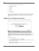
Configuring the GbE Interconnect Switch using the Menu-driven Interface To retain any configuration changes permanently in NVRAM: 1. Highlight Save Changes on the main menu. 2. Press the Enter key. The following screen is displayed to verify that your new settings have been saved to NVRAM. After the configuration settings have been saved to NVRAM, they become the default settings for the GbE Interconnect Switch. These settings are then used every time the GbE Interconnect Switch is rebooted.
Configuring the GbE Interconnect Switch using the Menu-driven Interface Managing User Accounts After logging on to the GbE Interconnect Switch for the first time, you need to set up at least one user account with Root privileges. You can set up a maximum of eight users on a GbE Interconnect Switch. There are three levels of user access rights: Root, User+, and User. Some menu selections available to users with Root privileges may not be available to those with User+ and User privileges.
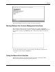
Configuring the GbE Interconnect Switch using the Menu-driven Interface Adding a User Account To create a new user account: 1. Highlight User Accounts Management on the main menu. 2. Press the Enter key. The Setup User Accounts screen is displayed. 3. Using the spacebar, toggle the Action field to Add. 4. Type the user’s name in the Username field. 5. Type an initial password for the user in the New Password field. IMPORTANT: Passwords used to access the GbE Interconnect Switch are case-sensitive. 6.
Configuring the GbE Interconnect Switch using the Menu-driven Interface Updating a User Account Information To update a user password or privilege level: 1. Highlight User Accounts Management on the main menu. 2. Press the Enter key. The Setup User Accounts screen is displayed. A listing of all current user accounts and access levels is displayed. 3. Toggle the Action field to Update. 4. Type the user name for the account you want to change in the Username field. 5.
Configuring the GbE Interconnect Switch using the Menu-driven Interface Deleting a User Account To prevent accidental deletion of all of the users with Root privilege, the menu-driven interface does not allow you delete the current logged-on user. To delete a user account: 1. Highlight User Accounts Management on the main menu. 2. Press the Enter key. The Setup User Accounts screen displays a list of all current users and access levels. 3. Toggle the Action field to Delete. 4.
Configuring the GbE Interconnect Switch using the Menu-driven Interface • Change the default SNMP community strings in the GbE Interconnect Switch and set the access rights of these community strings. Refer to the “Configuring SNMP/RMON Manager” section later in this chapter.
Configuring the GbE Interconnect Switch using the Menu-driven Interface The fields listed under the Current Switch IP Settings heading are those that are currently being used by the GbE Interconnect Switch. The fields listed under the New Switch IP Settings heading are those that will be used after the GbE Interconnect Switch has been rebooted. 3. Toggle the Get IP From field to choose from Manual, BOOTP, or DHCP. This action selects how the GbE Interconnect Switch will be assigned an IP address.
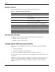
Configuring the GbE Interconnect Switch using the Menu-driven Interface Displaying Basic GbE Interconnect Switch Information You can display basic information about the GbE Interconnect Switch including: the type of switch, any external modules that are installed, and the MAC address (assigned by the factory and unchangeable) for that GbE Interconnect Switch. In addition, the boot PROM and firmware version numbers display. This information is helpful in monitoring PROM and firmware updates.
Configuring the GbE Interconnect Switch using the Menu-driven Interface — Firmware Build Date-#—Identifies the firmware build date and build number. — Hardware Version—Identifies the version number of the GbE Interconnect Switch hardware build. — Configuration Save Time—Identifies the date and time the current settings were saved to the configuration file. — System UpTime—Identifies the time of the GbE Interconnect Switch bootup, if the current time has been set on the interconnect switch.
Configuring the GbE Interconnect Switch using the Menu-driven Interface To configure advanced GbE Interconnect Switch features: 1. Highlight ADVANCED SETTINGS at the bottom of the Switch Information menu. 2. Press the Enter key. The following screen is displayed.
Configuring the GbE Interconnect Switch using the Menu-driven Interface — IGMP Snooping—Toggle to enable or disable Internet Group Management Protocol (IGMP) Snooping. IGMP snooping enables the GbE Interconnect Switch to register IGMP packets being forwarded through the GbE Interconnect Switch in order to obtain multicast membership information from them and learn which ports contain multicast members. For additional information, refer to the “Configuring IGMP Snooping” section later in this chapter.
Configuring the GbE Interconnect Switch using the Menu-driven Interface Configuring Port Settings This section describes how to configure the following port settings: port name, speed-duplex parameter, and flow control state. Refer to the “Configuring Port Security” section later in this chapter for information on how to set the port security parameters. The speed-duplex parameter for each port can be set to 1000M/Full, 100M/Full, 100M/Half, 10M/Full, 10M/Half, or Auto.
Configuring the GbE Interconnect Switch using the Menu-driven Interface 7. Toggle the Speed/Duplex field to select the speed and duplex state of the port. The Auto setting allows the port to automatically determine the fastest settings that the device the port is connected to can handle. The other options are 1000M/Full, 100M/Full, 100M/Half, 10M/Full, or 10M/Half. There is no automatic adjustment of port settings with any option other than Auto. 8. Toggle Flow Control to On or Off. 9. Highlight APPLY. 10.
Configuring the GbE Interconnect Switch using the Menu-driven Interface Configuring Restart Port Ingress Bandwidth To configure restart port ingress bandwidth: 1. Highlight Configure Restart Port Ingress Bandwidth on the Bandwidth Configuration menu. 2. Press the Enter key. The following screen is displayed. 3. Toggle the Action field to Add/Modify. NOTE: To delete an entry, toggle the Action field to Delete. 4. Type a port number in the Port field. 5.
Configuring the GbE Interconnect Switch using the Menu-driven Interface Displaying Current Port Ingress Bandwidth To view the current port ingress bandwidth settings: 1. Highlight Display Current Port Ingress Bandwidth on the Bandwidth Configuration menu. 2. Press the Enter key. The following screen is displayed. This read-only screen displays current ingress bandwidth information.
Configuring the GbE Interconnect Switch using the Menu-driven Interface Configuring Restart Port Egress Bandwidth To configure port egress bandwidth: 1. Highlight Configure Restart Port Egress Bandwidth on the Bandwidth Configuration screen. 2. Press the Enter key. The following screen is displayed. 3. Toggle the Action field to Add/Modify. NOTE: To delete an entry, toggle the Action field to Delete. 4. Type a destination port in the Port field. 5.
Configuring the GbE Interconnect Switch using the Menu-driven Interface Displaying Current Port Egress Bandwidth Settings To view port egress bandwidth settings: 1. Highlight Display Current Port Egress Bandwidth on the Bandwidth Configuration menu. 2. Press the Enter key. The following screen is displayed. This read-only screen displays current egress bandwidth information. Configuring Spanning Tree Protocol IEEE 802.
Configuring the GbE Interconnect Switch using the Menu-driven Interface The switch sends BPDUs to communicate and construct the spanning-tree topology. All switches connected to the LAN on which the packet is transmitted will receive the BPDU. BPDUs are not directly forwarded by the switch, but the receiving switch uses the information in the frame to calculate a BPDU, and if the topology changes, initiates a BPDU transmission.
Configuring the GbE Interconnect Switch using the Menu-driven Interface Setting Spanning Tree Parameters at the Switch Level IMPORTANT: The factory default settings should cover the majority of installations. HP recommends that you keep the default settings as set at the factory unless it is absolutely necessary to change them. To globally configure the Spanning Tree Protocol (STP) on the GbE Interconnect Switch: 1. Highlight Configure Spanning Tree Protocol on the Configuration menu. 2.
Configuring the GbE Interconnect Switch using the Menu-driven Interface — Priority—A priority for the GbE Interconnect Switch can be set from 0 to 65,535. Zero indicates the highest priority. The priority number is used in the voting process between switches on the network to determine which switch will be the root switch. A low number indicates a high priority, and a higher probability that this GbE Interconnect Switch will be elected as the root GbE Interconnect Switch.
Configuring the GbE Interconnect Switch using the Menu-driven Interface Setting Spanning Tree Parameters on the Port Level Once STP is enabled on the switch, you can configure ports to participate in the spanning tree domain, by enabling or disabling the STP function on a per port basis. Ports can also be configured in STP bypass mode (fast forward mode) that allows the port to skip the initial STP states (listening and learning) before enabling it in the forwarding state. To define individual ports: 1.
Configuring the GbE Interconnect Switch using the Menu-driven Interface Configuring Static (Destination Address) Filtering Table The GbE Interconnect Switch uses a filtering database to segment the network and control communications between segments. It can also filter packets off the network for intrusion control. Static filtering entries can be made by MAC address. Each port on the GbE Interconnect Switch is a unique collision domain.
Configuring the GbE Interconnect Switch using the Menu-driven Interface 2. Press the Enter key. The following menu is displayed. The Configure Static (Destination-Address Filtering) Table menu allows you to access screens to create, modify, and delete both the Static Unicast Filtering Table and the Static Multicast Filtering Table. Adding Unicast Filter Actions To configure the Static Unicast Table: 1.
Configuring the GbE Interconnect Switch using the Menu-driven Interface NOTE: To delete the unicast filter action for a VLAN, toggle the Action field to Delete. 4. Type the VID in the VLAN ID field. 5. Type the MAC address to be statically entered in the forwarding table in the MAC Address field. 6. Toggle the Type field to Permanent or DeleteOnReset, to set the unicast filter type. Permanent maintains the filter permanently, until reconfigured. DeleteOnReset deletes the filter when the port is reset. 7.
Configuring the GbE Interconnect Switch using the Menu-driven Interface 6. Set the multicast group membership of each port by highlighting the (E/-) field using the arrow keys, and then toggling between E, F, or a dash (—) using the spacebar. — E (Egress Member)—Specifies that the port is a static member of the multicast group. Egress Member Ports transmit traffic for the multicast group.
Configuring the GbE Interconnect Switch using the Menu-driven Interface • Forbidden Non-member—These ports are not a member of the VLAN and are also forbidden from joining a VLAN dynamically when GVRP is enabled. If ingress filtering is enabled for a port, the interconnect switch examines the VLAN information in the packet header (if present) and decides whether or not to forward the packet. The VID should match the PVID of that port, otherwise, that incoming packet is discarded.
Configuring the GbE Interconnect Switch using the Menu-driven Interface To edit VLAN definitions and to configure port settings for IEEE 802.1Q VLAN support: 1. Highlight Configure VLANs on the Configuration menu. 2. Press the Enter key. The following menu is displayed. Creating an 802.1Q Static VLAN To create an 802.1Q VLAN: 1. Highlight Configure Static VLAN Entry on the IEEE 802.1Q VLANs Configuration menu. 2. Press the Enter key. The following screen is displayed. 3.
Configuring the GbE Interconnect Switch using the Menu-driven Interface 4. Type a name for the new VLAN in the VLAN Name field. 5. Set the 802.1Q VLAN membership for each port by highlighting the Egress/Forbidden field using the arrow keys, and then toggling between E, F, and the dash (—) using the spacebar. — E (Egress Member)—Specifies the port as being a static member of the VLAN. Egress Member Ports are ports that will be transmitting traffic for the VLAN. These ports can be either tagged or untagged.
Configuring the GbE Interconnect Switch using the Menu-driven Interface Characteristics of a PVID include: • By default, the PVID of all ports is the same as the VID of DEFAULT_VLAN, which is equal to 1. • When a user creates an untagged 802.1Q VLAN and assigns a port, the PVID will be changed to the VID of that 802.1Q VLAN. • For a tagged port, the PVID will be the same as the VID of the IEEE 802.1Q VLAN to which this port was first assigned. • If the first IEEE 802.
Configuring the GbE Interconnect Switch using the Menu-driven Interface 5. Highlight APPLY. 6. Press the Enter key. IMPORTANT: To save the configuration settings permanently, you must enter them into NVRAM using the Save Changes option on the main menu. Refer to the “Saving Changes” section earlier in this chapter.
Configuring the GbE Interconnect Switch using the Menu-driven Interface To set ingress filtering on a port: 1. Highlight Configure Port Ingress Filter on the IEEE 802.1Q VLANs Configuration menu. 2. Press the Enter key. The following screen is displayed. 3. Type the range of port numbers you want to configure in the Configure Port fields. 4. Toggle between On and Off in the Ingress Filter field.
Configuring the GbE Interconnect Switch using the Menu-driven Interface Configuring GVRP This section describes how to configure GVRP on a per port basis. For information on how to set GVRP globally on the GbE Interconnect Switch, refer to the “Configuring Advanced GbE Interconnect Switch Features” section earlier in this chapter. GARP VLAN Registration Protocol (GVRP) is a Generic Attribute Registration Protocol (GARP) application that provides 802.
Configuring the GbE Interconnect Switch using the Menu-driven Interface To enable a port to dynamically become a member of a VLAN: 1. Highlight Configure Port GVRP Settings on the IEEE 802.1Q VLANs Configuration menu. 2. Press the Enter key. The following screen is displayed. 3. Type the range of ports to be configured in the Configure Port fields. 4. Toggle the GVRP State to On. 5. Highlight APPLY. 6. Press the Enter key.
Configuring the GbE Interconnect Switch using the Menu-driven Interface Configuring IGMP Snooping This section describes how to configure IGMP snooping on a VLAN ID. For information on how to set IGMP globally on the GbE Interconnect Switch and how to set the IGMP filter mode for processing multicast packets, refer to the “Configuring Advanced GbE Interconnect Switch Features” section earlier in this chapter.
Configuring the GbE Interconnect Switch using the Menu-driven Interface To configure IGMP Snooping: 1. Highlight Configure IGMP Snooping on the Configuration menu. 2. Press the Enter key. The IGMP Snooping Settings screen is displayed. The top line displays if IGMP Snooping is enabled or disabled globally on the GbE Interconnect Switch. If IGMP Snooping is enabled, you can set the following: — Action—Toggle to Add/Modify. — VLAN ID—Type the VLAN ID on which you want to enable IGMP snooping.
Configuring the GbE Interconnect Switch using the Menu-driven Interface Configuring Port Trunking This section describes how to configure port trunking. For information on how to set the trunk load-sharing algorithm parameter, refer to the “Configuring Advanced GbE Interconnect Switch Features” section earlier in this chapter. Port trunking allows several ports to be grouped together to act as a single link. This provides a bandwidth that is a multiple of a single link bandwidth.
Configuring the GbE Interconnect Switch using the Menu-driven Interface • The Spanning Tree algorithm views port trunk ports as a single Spanning Tree port. The Spanning Tree port is represented by the master logical port. • If the VLAN settings of the master logical port are changed, the VLAN settings of all members of that port trunk are changed similarly. • If the IGMP snooping configuration for any port trunk member is changed, the IGMP snooping settings for all port trunk members are changed.
Configuring the GbE Interconnect Switch using the Menu-driven Interface 3. After making your changes, highlight APPLY. 4. Press the Enter key. IMPORTANT: To save the configuration settings permanently, you must enter them into NVRAM using the Save Changes option on the main menu. Refer to the “Saving Changes” section earlier in this chapter.
Configuring the GbE Interconnect Switch using the Menu-driven Interface To configure port mirroring: 1. Highlight Configure Port Mirroring on the Configuration menu. 2. Press the Enter key. The following screen is displayed. 3. In the Source Port field, toggle to the number of the port from which you want to copy frames. 4. In the Source Direction field, toggle to the desired direction: Ingress, Egress, or Ingress & Egress. 5.
Configuring the GbE Interconnect Switch using the Menu-driven Interface Configuring Thresholds for Broadcast, Multicast, DA-Unknown Storm Prevention or Monitoring The GbE Interconnect Switch allows you to set the threshold (in packets per second) for three types of storms: broadcast, multicast, and one where the packet destination address (DA) is unknown. The higher the threshold, the more packets the GbE Interconnect Switch can accept per second.
Configuring the GbE Interconnect Switch using the Menu-driven Interface Configuring Class of Service, Default Port Priority, and Traffic Class This section describes how to configure class of service, default port priority, and traffic class. For information on how to set the class of service queue options, refer to the “Configuring Advanced GbE Interconnect Switch Features” section earlier in this chapter.
Configuring the GbE Interconnect Switch using the Menu-driven Interface Setting Class of Service To configure Class of Service: 1. Highlight Configure Class of Service on the Configure Class of Service, Default Priority and Traffic Class menu. 2. Press the Enter key. The following screen is displayed. The Class of Service Configuration screen allows you to set the following features: — Max.
Configuring the GbE Interconnect Switch using the Menu-driven Interface Setting Port Priority To assign port priority: 1. Highlight Configure Default Priority on the Configure Class of Service, Default Priority and Traffic Class menu. 2. Press the Enter key. The following screen is displayed. 3. Type the port range in the Configure Port fields. 4. Type the port priority in the Default Priority field. 5. Highlight APPLY. 6. Press the Enter key.
Configuring the GbE Interconnect Switch using the Menu-driven Interface Setting Traffic Class To configure traffic class: 1. Highlight Configure Traffic of Class on the Configure Class of Service, Default Priority and Traffic Class menu. 2. Press the Enter key. The following screen is displayed. 3. Toggle the Priority fields to set the traffic class for the eight levels of priority for the GbE Interconnect Switch. Class values are from 0 to 3. 4. Highlight APPLY. 5. Press the Enter key.
Configuring the GbE Interconnect Switch using the Menu-driven Interface Configuring Port Security To configure security for a specified port or range of ports on the GbE Interconnect Switch: 1. Highlight Configure Port Security on the Configuration menu. 2. Press the Enter key. The following screen is displayed. 3. Toggle the View Ports field to the port range that you want to view. 4. Type the port number or range of numbers to configure in the Configure Port fields. 5.
Configuring the GbE Interconnect Switch using the Menu-driven Interface Configuring Priority MAC Addresses To configure a priority MAC address for a specified VLAN on the GbE Interconnect Switch: 1. Highlight Configure Priority MAC Addresses on the Configuration menu. 2. Press the Enter key. The following screen is displayed. 3. Toggle to Add/Modify in the Action field. 4. Type the VLAN ID in the VLAN ID field. 5.
Configuring the GbE Interconnect Switch using the Menu-driven Interface Configuring GbE Interconnect Switch Serial Port A local console running a terminal emulation program can be connected directly to the GbE Interconnect Switch via the RS-232 serial (console) port on the front of the interconnect switch.
Configuring the GbE Interconnect Switch using the Menu-driven Interface — Stop Bits—Toggle to specify the number of bits that indicate when a serial word ends. The default value is 1 bit. — Auto-Logout—Toggle to specify the length of time a management session can be idle. When this time has expired, the GbE Interconnect Switch management agent will disconnect the user. The default value is 10 minutes. — Serial Port For—Toggle to select Console or SLIP.
Configuring the GbE Interconnect Switch using the Menu-driven Interface IMPORTANT: If the system clock is set and power is lost to the interconnect switch, manual time settings are reset to factory defaults when the interconnect switch is powered on. If this occurs, manually reset the date and time. If SNTP is configured, losing power has no effect, so no manual resetting of time is required. To configure time settings: 1. Highlight Configure Time on the Configuration menu. 2. Press the Enter key.
Configuring the GbE Interconnect Switch using the Menu-driven Interface — SNTP—Select Disabled or Enabled. The default is Disabled. — SNTP Server Primary—Type the IP address for the primary SNTP server. — SNTP Server Secondary—Type the IP address for the secondary SNTP server — SNTP Poll Interval—Type the polling interval (in seconds) for requesting the time from the server. A number from 30 to 99999 is allowed. The default is 720.
Configuring the GbE Interconnect Switch using the Menu-driven Interface Monitoring GbE Interconnect Switch Functions The GbE Interconnect Switch provides extensive network monitoring capabilities. To display the network data compiled by the GbE Interconnect Switch: 1. Highlight Network Monitoring on the main menu. 2. Press the Enter key. The following menu is displayed.
Configuring the GbE Interconnect Switch using the Menu-driven Interface Monitoring Port Utilization To view the port utilization of all the ports on the GbE Interconnect Switch: 1. Highlight Port Utilization on the Network Monitoring Menu. 2. Press the Enter key. The following screen is displayed. The Port Utilization screen displays the number of packets transmitted and received per second and calculates the percentage of the total available bandwidth being used on the port (displayed under %Util.). 3.
Configuring the GbE Interconnect Switch using the Menu-driven Interface Monitoring Trunk Utilization To view the trunk utilization of all the ports on the GbE Interconnect Switch: 1. Highlight Trunk Utilization on the Network Monitoring Menu. 2. Press the Enter key. The following screen is displayed.
Configuring the GbE Interconnect Switch using the Menu-driven Interface Monitoring Port Error Packets To view the error statistics for a port: 1. Highlight Port Error Packets on the Network Monitoring Menu. 2. Press the Enter key. The following screen is displayed. The Packet Error Statistic screen displays the following for received frames: — CRC Error—Counts Cyclic Redundancy Check (CRC) errors.
Configuring the GbE Interconnect Switch using the Menu-driven Interface — Ex. Coll.—Counts the number of frames that experienced 16 collisions during transmission and were aborted. — Single Coll.—Counts the number frames that experienced exactly one collision during transmission. — Coll.—Counts the number of collisions that occurred during the transmission of a frame. 3. Toggle the Port field to the number of the port to be viewed. 4.
Configuring the GbE Interconnect Switch using the Menu-driven Interface Monitoring MAC Address Forwarding Table To view the MAC address forwarding table: 1. Highlight Browse MAC Address on the Network Monitoring Menu. 2. Press the Enter key. The following screen is displayed. 3. Toggle the Browse By field between ALL, MAC Address, Port, and VLAN. This option sets a filter to determine which MAC addresses from the forwarding table are displayed. ALL specifies no filter.
Configuring the GbE Interconnect Switch using the Menu-driven Interface Monitoring GbE Interconnect Switch History To view the GbE Interconnect Switch history log: 1. Highlight Switch History from the Network Monitoring Menu. 2. Press the Enter key. The following screen is displayed. The Switch History screen displays the GbE Interconnect Switch events and health status. To scroll through the log 2-58 • Press the Ctrl+N keys to scroll to the next page.
Configuring the GbE Interconnect Switch using the Menu-driven Interface Monitoring IGMP Snooping IGMP Snooping allows the GbE Interconnect Switch to read the Multicast Group IP address and the corresponding MAC address from IGMP packets that pass through the GbE Interconnect Switch. To view the IGMP Snooping table: 1. Highlight IGMP Snooping on the Network Monitoring Menu. 2. Press the Enter key. The following screen is displayed. 3. Type the VLAN name in the VID field. 4.
Configuring the GbE Interconnect Switch using the Menu-driven Interface Monitoring Dynamic Group Registration Table To view the Dynamic Group Registration Table: 1. Highlight Dynamic Group Registration Table on the Network Monitoring Menu. 2. Press the Enter key. The following screen is displayed. The Dynamic Group Registration Table displays filtering information for VLANs configured into the bridge by local or network management, or learned dynamically.
Configuring the GbE Interconnect Switch using the Menu-driven Interface Monitoring VLAN Status To view the VLAN Status table: 1. Highlight VLAN Status on the Network Monitoring Menu. 2. Press the Enter key. The following screen is displayed. The VLAN Status window displays which VLAN ports are egress and which ports are untagged.
Configuring the GbE Interconnect Switch using the Menu-driven Interface The authentication protocol ensures that both the switch SNMP agent and the remote user SNMP application program discard packets from unauthorized users. SNMP (version 1) implements a form of security by requiring that each request include a “community string.” A community string is an arbitrary string of characters used as a “password” to control access to the GbE Interconnect Switch.
Configuring the GbE Interconnect Switch using the Menu-driven Interface The following parameters can be set: — SNMP Community String—Displays the community string that is included on SNMP request and traps sent to and from the GbE Interconnect Switch. If the receiver of a request or trap does not recognize the community string, the request or trap is ignored. SNMP allows up to four community strings to be defined. The community strings “public” and “private” are defined by default.
Configuring the GbE Interconnect Switch using the Menu-driven Interface Using System Utilities Trivial File Transfer Protocol (TFTP) services allow the switch firmware to be upgraded by transferring a new firmware file from a TFTP server to the GbE Interconnect Switch.
Configuring the GbE Interconnect Switch using the Menu-driven Interface Upgrading Firmware from a TFTP Server To upgrade the firmware from a TFTP server: 1. Highlight Upgrade Firmware from TFTP Server on the Switch Utilities menu. 2. Press the Enter key. The following screen is displayed. 3. Type the IP address of the TFTP server in the Server IP Address field. IMPORTANT: The TFTP server must be on the same IP subnet as the GbE Interconnect Switch. 4.
Configuring the GbE Interconnect Switch using the Menu-driven Interface Downloading Configuration File from a TFTP Server IMPORTANT: Configuration files used in the earlier version of the switch module (firmware version 1.0) are not supported by the present version (firmware version 2.0). The switch module Information window displays the firmware version. A configuration file can be downloaded from a TFTP server to the switch module. This file is then used by the switch module to configure itself.
Configuring the GbE Interconnect Switch using the Menu-driven Interface Saving Settings to a TFTP Server After completing the final configuration for the GbE Interconnect Switch, HP highly recommends that you save the GbE Interconnect Switch configuration file to TFTP server storage. To save the GbE Interconnect Switch configuration file to a TFTP server: 1. Highlight Save Settings to TFTP Server on the Switch Utilities menu. 2. Press the Enter key. The following screen is displayed. 3.
Configuring the GbE Interconnect Switch using the Menu-driven Interface Saving the History Log to a TFTP Server To save the History Log on a TFTP server: 1. Highlight Save History Log to TFTP Server on the Switch Utilities menu. 2. Press the Enter key. The following screen is displayed. 3. Type the IP address of the TFTP server in the Server IP Address field. 4. Type the port number of the TFTP server you wish to connect in the Server TFTP Port Number field. 5.
Configuring the GbE Interconnect Switch using the Menu-driven Interface Performing a Ping Test To test the connection with another network device using Ping: 1. Highlight Ping Test on the Switch Utilities menu. 2. Press the Enter key. The following screen is displayed. 3. Type the IP address of the network device to be pinged in the IP Address field. 4. Type the number of test packets to be sent (three is usually enough) in the Number of Repetitions field. 5. Highlight START. 6. Press the Enter key.
Configuring the GbE Interconnect Switch using the Menu-driven Interface Rebooting the GbE Interconnect Switch The GbE Interconnect Switch reboot options are: • Reboot—Restarts the GbE Interconnect Switch. Any configuration settings not saved using Save Changes from the main menu are lost. The GbE Interconnect Switch configuration is restored to the last configuration saved in NVRAM.
Configuring the GbE Interconnect Switch using the Menu-driven Interface 3. Highlight the appropriate selection. 4. Press the Enter key. The following screen is displayed. 5. Highlight Yes and press the Enter key. Logging Out To exit the setup pages, select Logout on the Main menu. The Account Login screen is displayed.
Index A F accounts, user 2-3 advanced settings 2-11 auto-logout 2-11 features 1-4 field-level help 1-4 firmware upgrades 2-65 B G backpressure 2-12 bandwidth, configuring 2-14 basic settings 2-9 Bootstrap Protocol (BOOTP) IP address assignment 2-7, 2-8 broadcast storm configuring threshold 2-41 grounding v grounding plug v group address filter mode 2-12 GVRP (GARP VLAN Registration Protocol) settings 2-12, 2-33 C help resources vi history, switch saving with TFTP server 2-68 history, switch 2-58 H
Index MAC addresses configuring 2-47 monitoring 2-57 manual assignment of IP addresses 2-7, 2-8 mirroring of ports 2-39 monitoring switch functions 2-52 multicast filtering 2-35 multicast filtering, configuring 2-25 multicast storm, configuring threshold 2-41 N navigation features 1-4 Network Monitoring Menu 2-52 new users, setting up 2-3 NVRAM (non-volatile RAM) 2-1 S saving changes 2-1 scheduling mechanism for CoS queues 2-12 security configuring port 2-46 size of packets, monitoring 2-56 SLIP (serial