
ProLiant BL p-Class GbE Interconnect Switch Overview
18
Switch security
• Password protected multi-level user accounts supported on all management interfaces
• Configurable user interface idle time-out period
• Ability to disable web-based and Telnet access to the switch user interfaces
• 256 Port-based IEEE 802.1Q tagged VLANs per switch (512 per server blade enclosure)
• Ability to specify the IP-based management stations that is allowed to access the switch
• Unicast and multicast static MAC address packet filtering table (layer 2 access control list)
• Restriction on the maximum number of MAC addresses learned on a per port basis
Switch availability
• Front-mounted, hot-swappable switch with configuration retention and no need to cable/recable when removing
• Redundant switches per server blade enclosure
• Redundant uplink ports per switch
• Redundant front panel management/diagnostic ports per switch
• Redundant crosslinks for switch to switch communication and failover scenarios within the server blade enclosure
• Redundant pairs of network adapters per server routed to different switches
• Redundant N+N hot-plug redundant power to each switch
• Redundant N+1 on-board cooling per switch
• IEEE 802.3ad automatic multi-link load balancing and link failover (excluding LACP)
• Load balancing of unicast traffic
• ProLiant network adapter teaming
• Redundant configurable community strings and SNMP trap manager hosts
• Redundant configurable SNTP servers
Switch ports per server blade enclosure
• Four external 10/100T Fast Ethernet ports and four external 10/100/1000T (C-GbE) or 1000SX (F-GbE) Gigabit Ethernet
ports, all on a pair of hot-pluggable rear-mounted interconnect modules
• Four external 10/100T Fast Ethernet ports on switch front panels
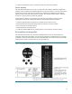
• Two external DB-9 serial ports on switch front panels (one per switch)
• 32 internal 10/100 Fast Ethernet ports to server blade network adapters (4 per server bay)
• Two internal 10/100 Gigabit Ethernet inter-switch crosslinks for switch to switch communication and failover scenarios
• I
2
C Switch to management module communications
• All external Ethernet ports may be used for data, switch and iLO management, and/or PXE remote configuration.
• All internal Ethernet signals routed as Ethernet across individual CAT5e signal traces
• 12 RJ-45 (C-GbE) or 4 LC fiber + 8 RJ-45 (F-GbE) external Ethernet port connectors
Switch physical and environmental
• AC power input (at server blade system level)
• Direct facility -48 DC power input
• 40 Typical and 50 maximum power consumption per switch (watts)
• Local front power reset/power cycle button on each switch
• Remote reset/power cycle via user interface
• 10 to 35 operating and -30 to 60 storage temperature (Celsius)
• 20% to 80% operating and 5% to 95% storage relative humidity
• FCC Class A, ICES-003 Class A, AS/NZS 3548 Class A, and VCCI Class A electromagnetic interference (EMI) certifications
• UL/CUL and CE safety certifications
• 11.5 pounds per interconnect switch and interconnect module