HP ProLiant BL p-Class GbE Interconnect Switch Web-based Interface Reference Guide February 2003 (First Edition) Part Number 322606-001
© 2003 Hewlett-Packard Development Company, L.P. Microsoft®, Windows®, and Windows NT® are U.S. registered trademarks of Microsoft Corporation. Netscape Navigator is a U.S. trademark of Netscape Communications Corporation. Hewlett-Packard Company shall not be liable for technical or editorial errors or omissions contained herein. The information in this document is provided “as is” without warranty of any kind and is subject to change without notice.
Contents About This Guide Technician Notes...........................................................................................................................................v Where to Go for Additional Help.................................................................................................................vi Telephone Numbers ...............................................................................................................................
Contents Configuring Bandwidth ...........................................................................................................................2-30 Configuring the Restart Ingress Bandwidth Settings ........................................................................2-31 Displaying the Current Ingress Bandwidth Table .............................................................................2-31 Configuring the Restart Egress Bandwidth Settings .............................................
About This Guide This reference guide can be used when configuring the GbE Interconnect Switch using the Web-based interface. WARNING: To reduce the risk of personal injury from electric shock and hazardous energy levels, only authorized service technicians should attempt to repair this equipment. Improper repairs can create conditions that are hazardous. Technician Notes WARNING: Only authorized technicians trained by HP should attempt to repair this equipment.
About This Guide NOTE: Any indications of component replacement or printed wiring board modifications may void any warranty.
1 Overview Introduction The GbE Interconnect Switch offers an embedded Web-based (HTML) interface that allows you to manage each GbE Interconnect Switch from anywhere on the network through a standard browser, such as Netscape Navigator or Microsoft Internet Explorer. The Web browser acts as a universal access tool and can communicate directly with the GbE Interconnect Switches using the HTTP protocol. NOTE: Your browser window may differ from the screen shots in this guide.
Overview Connecting to the GbE Interconnect Switch the First Time Before you can connect to a GbE Interconnect Switch using the Web-based interface, you must set the IP address on the GbE Interconnect Switch. By default, if there is a DHCP server on the network, a GbE Interconnect Switch obtains the IP address automatically. If there is no DHCP server on the network, configure the IP addresses of the GbE Interconnect Switches using the following instructions.
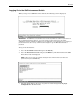
Overview Logging On to the GbE Interconnect Switch When you log on to a GbE Interconnect Switch, the following screen is displayed. IMPORTANT: The GbE Interconnect Switch does not have any initial user names or passwords set. HP recommends that after logging on, you create at least one Root-level user as the switch administrator. (Refer to Table 2-1 in Chapter 2 for an explanation of user privileges.
Overview 4. Press the Enter key. The Configuration menu is displayed. 5. Highlight Configure IP Address from the Configuration menu. 6. Press the Enter key. The Remote Management Setup screen is displayed. The Remote Management Setup screen lets you specify how the GbE Interconnect Switch will be assigned an IP address, which allows an in-band network management system (for example, Telnet) client to find it on the network.
Overview — Manual—This option allows the entry of an IP address, subnet mask, and default gateway for the GbE Interconnect Switch. The data in these fields should be of the form xxx.xxx.xxx.xxx, where each xxx is a number between 0 and 255. This address should be a unique address on the network assigned for use by the Network Administrator. The fields that require entries under this option include: — Subnet Mask—A Bitmask that determines the extent of the subnet that the GbE Interconnect Switch is on.
Overview After the configuration settings have been saved to NVRAM, they become the default settings for the GbE Interconnect Switch. These settings are then used every time the GbE Interconnect Switch is rebooted. IMPORTANT: After saving your final configuration, HP highly recommends that you save the configuration image to TFTP server storage. Refer to the “Uploading a Configuration File to TFTP Server” section in Chapter 2 for more information.
Overview 4. Click Log In. The Enter Network Password dialog box for the GbE Interconnect Switch is displayed. IMPORTANT: The GbE Interconnect Switch does not have any initial user names or passwords set. HP recommends that after logging on, create at least one Root-level user as the switch administrator. (Refer to Table 2-1 in Chapter 2, for an explanation of user privileges.) If you forget your password after it has been set up, call HP Customer Support for assistance. 5.
Overview The active graphic of the GbE Interconnect Switch allows you to monitor the GbE Interconnect Switch status. Graphical LEDs display current link speed and activity. Graphical RJ-45 connectors allow you to display statistics for individual ports. In addition, the current time is displayed, once it is configured on the GbE Interconnect Switch. Refer to the section, “Configuring GbE Interconnect Switch Date and Time” in Chapter 2, for information on how to set the date and time.
2 Configuring the GbE Interconnect Switch using the Web-based Interface Overview This chapter describes how to configure the GbE Interconnect Switch from the Web-based interface. Saving Changes The GbE Interconnect Switch has two types of memory: dynamic RAM and non-volatile RAM (NVRAM). Restarting the GbE Interconnect Switch erases all configuration settings in RAM and reloads the stored settings from NVRAM.
Configuring the GbE Interconnect Switch using the Web-based Interface 2. Click Save Changes. The Save Configuration window is displayed. 3. Click Save Configuration to save all the changes made in the current session to the NVRAM memory of the GbE Interconnect Switch. A message box is displayed when the save is completed. 4. Click OK. After the GbE Interconnect Switch configuration settings have been saved to NVRAM, they become the default settings for the GbE Interconnect Switch.
Configuring the GbE Interconnect Switch using the Web-based Interface To create a new user account: 1. Click the small square to the left of the Management folder on the main menu. The Management menus are displayed. 2. Click User Accounts. The following is displayed. The User Account Management window displays all current users for the GbE Interconnect Switch and their current access level. The User Account Modify Table allows you to enter user account information.
Configuring the GbE Interconnect Switch using the Web-based Interface 7. Click the drop-down arrow in the Access Right field to select the access level. The three access levels are User, User+, and Root. A Root user has full read/write access, while a User has read-only access. A User+ has the same privileges as a User, but with the added ability to restart the GbE Interconnect Switch. 8. Click Apply.
Configuring the GbE Interconnect Switch using the Web-based Interface Setting the Remote Management IP Interface Settings To access and manage the GbE Interconnect Switch from an SNMP-based Network Management System, or by using the Telnet protocol or the Web, you must first configure the remote management IP interface parameters.
Configuring the GbE Interconnect Switch using the Web-based Interface — Subnet Mask—The address mask that controls subnetting on your TCP/IP network — Default Gateway—The IP address of the device, usually a router, that handles connections to other subnets or other TCP/IP networks — VID—The VLAN ID (VID) number for the switch management port 2.
Configuring the GbE Interconnect Switch using the Web-based Interface To display and configure basic GbE Interconnect Switch information: 1. Select Switch Information from the Configuration menu. The following screen is displayed. The Switch Information (Basic Settings) window displays the following information: — Device Type—Displays the name of the GbE Interconnect Switch. — MAC Address—Identifies the Ethernet address for the GbE Interconnect Switch.
Configuring the GbE Interconnect Switch using the Web-based Interface — Hardware Version—Identifies the version number of the GbE Interconnect Switch hardware build. — System Up Time—Identifies the time of the GbE Interconnect Switch bootup, if the current time has been set on the interconnect switch. If the current time has never been set up on the interconnect switch, this field identifies the time since the switch module was booted up.
Configuring the GbE Interconnect Switch using the Web-based Interface 5. Click Apply. IMPORTANT: To save the configuration settings permanently, they must be entered into NVRAM using the Save Changes option on the Maintenance menu. Refer to the section, “Saving Changes,” earlier in this chapter. Configuring Advanced GbE Interconnect Switch Features You can configure advanced switch features including global settings for IGMP snooping, GVRP, Telnet status, Web status, SNTP, and others.
Configuring the GbE Interconnect Switch using the Web-based Interface The GbE Interconnect Switch enters into its forwarding table the mapping between the MAC address of the device and the Ethernet port to which the device is attached. This information is used to forward packets. This reduces the traffic congestion on the network, because packets are forwarded to the destination port only, instead of being forwarded to all ports.
Configuring the GbE Interconnect Switch using the Web-based Interface — Trunk Load Sharing Algorithm—Select one of the port trunk load sharing options, Source Addr, Destination Addr, or Both, to determine if load balancing decisions will be made based on the source MAC address, destination MAC address, or both addresses. — Backpressure— Select Enabled or Disabled to initiate or terminate backpressure flow control in and out of the switch.
Configuring the GbE Interconnect Switch using the Web-based Interface To configure port settings: 1. Select Port Configuration from the Configuration menu. The following screen is displayed. 2. Select the port you want to configure in the Port field. The port name displays in the Port Name field. 3. Select Enabled or Disabled in the State field.
Configuring the GbE Interconnect Switch using the Web-based Interface 4. Configure the Speed/Duplex setting for the port: IMPORTANT: If you have the ProLiant BL p-Class F-GbE Interconnect Kit option with the DualTSX Interconnect Modules, the management interface supports only 1000M/Full and Auto options for the Speed/Duplex fields for the Gigabit uplink ports. The fiber DualTSX Interconnect Module supports only 1000-Mb/s (Gigabit) speed, and not 10-Mb/s or 100-Mb/s.
Configuring the GbE Interconnect Switch using the Web-based Interface IMPORTANT: You cannot mirror a fast port onto a slower port. For example, if you try to mirror the traffic from a 1000-Mb/s port onto a 100-Mb/s port, you can cause throughput problems. The port from which you are copying frames must support an equal or lower speed than the port to which you are sending the copies. Also, the target port cannot be a member of a trunk group. To configure port mirroring: 1.
Configuring the GbE Interconnect Switch using the Web-based Interface Configuring Port Trunking This section describes how to configure port trunking. For information on how to set the trunk load-sharing algorithm parameter, refer to the “Configuring Advanced GbE Interconnect Switch Features” section earlier in this chapter. Port trunking allows several ports to be grouped together to act as a single link. This provides a bandwidth that is a multiple of a single link bandwidth.
Configuring the GbE Interconnect Switch using the Web-based Interface • If the IGMP snooping configuration for any port trunk member is changed, the IGMP snooping settings for all port trunk members are changed. • The port trunk takes precedence over any other setting. That is, the settings of trunked ports are the same as the master port settings. • When any trunked port becomes a non-trunked port, all of the port configurations are reset to default settings.
Configuring the GbE Interconnect Switch using the Web-based Interface Configuring IGMP Snooping This section describes how to configure IGMP snooping on a VLAN ID. For information on how to set IGMP globally on the GbE Interconnect Switch and how to set the IGMP filter mode for processing multicast packets, refer to the “Configuring Advanced GbE Interconnect Switch Features” section earlier in this chapter.
Configuring the GbE Interconnect Switch using the Web-based Interface To configure IGMP snooping: 1. Select IGMP Snooping from the Configuration menu. The following screen is displayed. 2. Select a VID number in the VLAN ID field. 3. Select Enabled in the State field. 4. In the Querier State field, select the IGMP version that will be used by the IGMP interface when making queries. Select from Non-Querier, V1-Querier, and V2-Querier. 5. In the Robustness Variable field, type a value between 1 and 255.
Configuring the GbE Interconnect Switch using the Web-based Interface STP communicates between switches on the network using Bridge Protocol Data Units (BPDUs). Each BPDU contains the following information: • The unique identifier of the switch that the transmitting switch currently believes is the root switch • The path cost to the root from the transmitting port • The port identifier of the transmitting port The switch sends BPDUs to communicate and construct the spanning-tree topology.
Configuring the GbE Interconnect Switch using the Web-based Interface Setting Spanning Tree Parameters on the Switch Level IMPORTANT: The factory default settings should cover the majority of installations. HP recommends that you keep the default settings as set at the factory unless it is absolutely necessary to change them.. To set STP parameters on the switch level: 1. Select STP Switch Settings from the Spanning Tree menu. The following screen is displayed.
Configuring the GbE Interconnect Switch using the Web-based Interface — Cost to Root—Displays the summation of all path costs between the current bridge and the root bridge via the root port. — Root Port—Displays the port on the current bridge that has the best path to reach the designated root bridge. — Root Priority (Sec)—Displays the priority of the current designated root bridge. — Bridge Max Age (6–40 Sec)—Type the maximum age. The range is 6 to 40 seconds.
Configuring the GbE Interconnect Switch using the Web-based Interface Setting Spanning Tree Parameters on the Port Level Once STP is enabled on the switch, you can configure ports to participate in the spanning tree domain, by enabling or disabling the STP function on a per port basis. Ports can also be configured in STP bypass mode (fast forward mode) that allows the port to skip the initial STP states (listening and learning) before enabling it in the forwarding state. To enable STP on the port level: 1.
Configuring the GbE Interconnect Switch using the Web-based Interface 6. In the Priority (0–255) field, type a port priority from 0 to 255. The lower the priority, the greater the probability that the port will be chosen as the root port. 7. In the ByPass field, select Yes or No. The bypass sets the forward delay timer to zero, thus bypassing the waiting time before the listening state. (This procedure is also known as fast forward.) 8. Click Apply after making changes to the settings.
Configuring the GbE Interconnect Switch using the Web-based Interface Adding Unicast Filter Actions To add unicast filter actions: 1. Select Unicast Filtering from the Static Filtering Table menu. The following screen is displayed. 2. In the VID field, type the VID number of the VLAN to which the MAC address belongs. 3. In the MAC Address field, type the MAC address from which packets will be statically filtered. 4. In the Type field, select the filter type, either Permanent or DeleteOnReset. 5.
Configuring the GbE Interconnect Switch using the Web-based Interface 6. Click Apply after making changes to the settings. IMPORTANT: To save the configuration settings permanently, you must enter them into NVRAM using the Save Changes option on the Maintenance menu. Refer to the section, “Saving Changes,” earlier in this chapter. Configuring VLANs A Virtual Local Area Network (VLAN) is a network topology configured according to a logical scheme rather than the physical layout.
Configuring the GbE Interconnect Switch using the Web-based Interface Default VLAN The GbE Interconnect Switch reserves one VLAN, VID 1, also called DEFAULT_VLAN. The factory default setting assigns all ports on the GbE Interconnect Switch to the default VLAN. As new VLANs are configured, their respective member ports are removed from the default VLAN. Characteristics of DEFAULT_VLAN include: • DEFAULT_VLAN is an IEEE 802.1Q Static VLAN with VID equal to 1. • DEFAULT_VLAN cannot be deleted.
Configuring the GbE Interconnect Switch using the Web-based Interface 2. Type the VLAN ID number of the VLAN you want to add in the VID field. The range is 1 to 4094. This field is grayed out in the Modify mode. 3. Type the name of the VLAN that is being created in the VLAN Name field. 4. In the Tag field, click the check box to designate the port as tagging. Leave the box unchecked for untagging. 5.
Configuring the GbE Interconnect Switch using the Web-based Interface • If the first IEEE 802.1Q VLAN to which the tagged port is assigned is deleted, the PVID will change to that of the second IEEE 802.1Q VLAN to which the port was assigned. • The PVID of a port can only be set to a VID of a VLAN for which the port is already a member. GARP VLAN Registration Protocol (GVRP) is a Generic Attribute Registration Protocol (GARP) application that provides 802.
Configuring the GbE Interconnect Switch using the Web-based Interface Ingress filtering is used to conserve bandwidth within the interconnect switch by dropping packets that are not on the same VLAN as the ingress port at the point of reception. This eliminates the subsequent processing of packets that will just be dropped by the destination port. To set the port VLAN ID (PVID) and enable GVRP for a port: 1. Select Port VLAN ID (PVID) from the VLANs menu. The following screen is displayed. The 802.
Configuring the GbE Interconnect Switch using the Web-based Interface 2. In the From and To fields, select the range of ports to be included in the settings. 3. In the PVID field, type the PVID. This tuning variable allows for subnetworks that are expected to lose a large number of packets. The PVID is used by the port to tag outgoing, untagged packets and to make filtering decisions about incoming packets.
Configuring the GbE Interconnect Switch using the Web-based Interface Configuring the Restart Ingress Bandwidth Settings To configure the restart ingress bandwidth settings for a port: 1. Select Restart Ingress Bandwidth from the Port Bandwidth menu. The following screen is displayed. 2. Select the desired port in the Port Num field. 3. Type a number between 1 and 127 in the Ingress Bandwidth (1–127 Units) field. 4. Click Apply. 5. Select Restart System from the Maintenance menu. 6.
Configuring the GbE Interconnect Switch using the Web-based Interface Configuring the Restart Egress Bandwidth Settings To configure egress bandwidth for a specific port: 1. Select Restart Egress Bandwidth from the Port Bandwidth menu. The following screen is displayed. 2. Select the desired port in the Port Num field. 3. Type a number between 1 and 127 in the Egress Bandwidth (1–127 Units) field. 4. Click Apply to save the change or addition. 5. Select Restart System from the Maintenance menu. 6.
Configuring the GbE Interconnect Switch using the Web-based Interface Configuring the Thresholds of Broadcast, Multicast, and DA-Storm Prevention or Monitoring The GbE Interconnect Switch allows you to set the threshold (in packets per second) for three types of storms: broadcast, multicast, and one where the packet destination address (DA) is unknown. The higher the threshold, the more packets the GbE Interconnect Switch can accept per second.
Configuring the GbE Interconnect Switch using the Web-based Interface Setting Port Priority To set the port priority: 1. Select Port Priority from the Configuration menu. The following screen is displayed. 2. Select the appropriate port in the From and To fields. 3. Type the priority in the Priority (0–7) field. 4. Click Apply to save the changes. IMPORTANT: To save the configuration settings permanently, you must enter them into NVRAM using the Save Changes option on the Maintenance menu.
Configuring the GbE Interconnect Switch using the Web-based Interface Setting Traffic Class To set the traffic class: 1. Select Class of Traffic from the Configuration menu. The following screen is displayed. The Configure Class of Traffic window allows you to configure traffic class priority by specifying the class value, from 0 to 3, of the eight levels of priority of the GbE Interconnect Switch. 2. Select the class value for each priority. 3. Click Apply to save the changes.
Configuring the GbE Interconnect Switch using the Web-based Interface Setting Class of Service To set the class of service: 1. Select Class of Service from the Configuration menu. The following screen is displayed. The Class of Service Configuration window allows you to set the maximum number of packets and the maximum allowable time a packet stays in the Class of Service (CoS) queue. 2. In the Max. Packets field, type a value between 0 and 255.
Configuring the GbE Interconnect Switch using the Web-based Interface Configuring Port Security To configure port security for a port or range of ports: 1. Select Port Security from the Configuration menu. The following screen is displayed. 2. Select the range of ports in the From and To fields. 3. Select Enabled in the Admin State field. 4. Type the maximum number of addresses in the Max. Address field. 5. Select the Mode that you want, either DeleteOnTimeout or DeleteOnReset. 6.
Configuring the GbE Interconnect Switch using the Web-based Interface Configuring Priority MAC Addresses To set the priority level for a MAC address: 1. Select Priority MAC Addresses from the Configuration menu. The following screens are displayed. 2. Type the VLAN ID in the VLAN ID field. 3. Type the MAC address for which priority on the GbE Interconnect Switch is to be established in the MAC Address field. 4. Type the priority level for the MAC address in the Priority Level field.
Configuring the GbE Interconnect Switch using the Web-based Interface Configuring GbE Interconnect Switch Serial Port A local console running a terminal emulation program can be connected directly to the GbE Interconnect Switch via the RS-232 serial (console) port on the front of the interconnect switch.
Configuring the GbE Interconnect Switch using the Web-based Interface 6. In the Auto-Logout field, select the length of time a management session can be idle. When this time has expired, the management agent of the GbE Interconnect Switch will disconnect the user. The default value is 10 minutes. 7. In the Serial Port For field, select Console or SLIP. 8. In the Local IP Address field, type the local IP address of the SLIP connection. 9.
Configuring the GbE Interconnect Switch using the Web-based Interface Setting the Current Time or Enabling SNTP To set the current time or enable SNTP: 1. Select Time Settings from the Configuration menu. 2. Select Current Time Settings. The following screen is displayed. The Current Time screen allows you to set the current time and date, enable SNMP, and set the SNMP parameters.
Configuring the GbE Interconnect Switch using the Web-based Interface — Current Time: Set Current Time allows you to manually set the current date and time. This screen is grayed out if SNTP state is enabled. To manually set the date and time, enter the following: — Year—Select the current year. — Month—Select the current month. — Day—Select of the current day of the month. — Time in HH MM—Select the current time in hh mm format. Leading zeros (0) are not required. 3.
Configuring the GbE Interconnect Switch using the Web-based Interface The Time Zone and DST screen allows you to set the time zone and daylight saving time information. The screen is divided into the following three sections: — Time Zone and DST Settings allows you to configure the following: — Daylight Saving Time State—Select Disabled, Repeating, or Annual to set if and how daylight saving time will be determined.
Configuring the GbE Interconnect Switch using the Web-based Interface IMPORTANT: To save the configuration settings permanently, you must enter them into NVRAM using the Save Changes option on the Maintenance menu. Refer to the section, “Saving Changes,” earlier in this chapter. Configuring the Security IP You can enter a list of IP addresses that are allowed to access the switch by means of SNMP, Telnet, and the Web. To specify which IP addresses are allowed to access the GbE Interconnect Switch: 1.
Configuring the GbE Interconnect Switch using the Web-based Interface The GbE Interconnect Switch has software, called an agent, that processes SNMP requests. The user program that makes the requests and collects the responses runs on the management station (a designated computer on the network). The SNMP agent and the user program both use the UDP/IP protocol to exchange packets.
Configuring the GbE Interconnect Switch using the Web-based Interface Configuring Trap Manager Traps are messages that alert you of events that occur on the GbE Interconnect Switch. The events can be as serious as a reboot (someone accidentally reset the interconnect switch), or less serious like a configuration file update. The GbE Interconnect Switch generates traps and sends them to the network manager (trap recipient).
Configuring the GbE Interconnect Switch using the Web-based Interface Monitoring GbE Interconnect Switch Functions The Web-based monitoring screens allow you to monitor the following GbE Interconnect Switch functions: • Port Utilization • Packets—Received (RX), UMB-cast (RX), Transmitted (TX) • Errors—Received (RX) and Transmitted (TX) • Size—Packet Size • Trunk Utilization • MAC Address Table • IGMP Snooping Table • Dynamic Group Registration • VLAN Status Table Monitoring the GbE Interc
Configuring the GbE Interconnect Switch using the Web-based Interface Monitoring Port Utilization To monitor port utilization, select Port Utilization from the Monitoring menu. The following screen is displayed. The Port Utilization window shows the percentage of the total available bandwidth being used on a specified port. The following information is displayed: • Utilization—Displays the percentage of the total bandwidth being used on the specified port.
Configuring the GbE Interconnect Switch using the Web-based Interface Monitoring Received (RX) Packets To monitor received packets, select Received (RX) Packets from the Packets menu. The following screens are displayed.
Configuring the GbE Interconnect Switch using the Web-based Interface The Rx Packets Analysis window displays the number of bytes and packets received on the port. The following information is displayed: • Time Interval—Select the frequency at which the information on the screen is refreshed. The setting is between 1s and 60s, where “s” stands for seconds. The default value is one second. • Record Number—Select the number of times that the GbE Interconnect Switch will be polled.
Configuring the GbE Interconnect Switch using the Web-based Interface The UMB-cast (RX) Packets window displays the number of good bytes and packets that were received by a unicast, multicast, or broadcast address. The following information is displayed: • Time Interval—Select the frequency at which the information on the screen is refreshed. The setting can be between 1s and 60s, where “s” stands for seconds. • Record Number—Select the number of times the GbE Interconnect Switch will be polled.
Configuring the GbE Interconnect Switch using the Web-based Interface Monitoring Transmitted (TX) Packets To monitor transmitted packets, select Transmitted (TX) Packets from the Packets menu. The following screens are displayed.
Configuring the GbE Interconnect Switch using the Web-based Interface The Tx Packets Analysis window displays the number of bytes and packets successfully sent from the port. The following information is displayed: • Time Interval—Select the frequency at which the information on the screen is refreshed. The setting can be between 1s and 60s, where “s” stands for seconds. The default value is one second. • Record Number—Select the number of times the GbE Interconnect Switch will be polled.
Configuring the GbE Interconnect Switch using the Web-based Interface The Rx Error Analysis window displays the number of errors received. The following information is displayed: 2-54 • Time Interval—Select the frequency at which the information on the screen is refreshed. The setting can be between 1s and 60s, where “s” stands for seconds. The default value is one second. • Record Number—Select the number of times the GbE Interconnect Switch will be polled. The setting can be between 20 and 200.
Configuring the GbE Interconnect Switch using the Web-based Interface Monitoring Transmitted (TX) Errors To monitor transmitted errors, select Transmitted (TX) Errors from the Errors menu. The following screens are displayed.
Configuring the GbE Interconnect Switch using the Web-based Interface The Tx Error Analysis window displays the number of errors that occurred during transmission. The following information is displayed: 2-56 • Time Interval—Select the frequency at which the information on the screen is refreshed. The setting can be between 1s and 60s, where “s” stands for seconds. The default value is one second. • Record Number—Select the number of times the GbE Interconnect Switch will be polled.
Configuring the GbE Interconnect Switch using the Web-based Interface Monitoring Packet Size To monitor packet size, select Packet Size from the Size menu. The following screens are displayed. The Rx Size Analysis window displays the number of packets received that were within a certain range of bytes in length. The following information is displayed: • Time Interval—Select the frequency at which the information on the screen is refreshed.
Configuring the GbE Interconnect Switch using the Web-based Interface • Record Number—Select the number of times the GbE Interconnect Switch will be polled. The setting can be between 20 and 200. The default value is 20. • 64—Displays the total number of packets (including bad packets) received that were 64 bytes in length (excluding framing bits but including FCS bytes).
Configuring the GbE Interconnect Switch using the Web-based Interface The Trunk Utilization window displays the port trunking groups and allows you to view graphs of three items for an individual port trunking group: the percentage of total available bandwidth being used by the group, the percentage of packets transmitted, and the percentage of packets being received per second. The following information is displayed: • ID—Identifies the group ID for the port trunking group.
Configuring the GbE Interconnect Switch using the Web-based Interface • Show/Hide—Select to display or hide Rx_Util, Tx_Util, R&Tx_Util information. • Apply—Select to apply any changes made to the Time Interval, Record Number, and Show/Hide fields. • Clear—Select to reset the counters. Monitoring MAC Address Forwarding Table To monitor the MAC Address Forwarding Table, select MAC Address Table from the Monitoring menu. The following screens are displayed.
Configuring the GbE Interconnect Switch using the Web-based Interface • MAC Address—Identifies the MAC address entered into the address table. • Port—Identifies the port that the MAC address corresponds to. • Learned—Identifies the method that the GbE Interconnect Switch used to discover the MAC address. • Next—Click this button to view the next page of the address table. Monitoring IGMP Snooping To monitor IGMP snooping, select IGMP Snooping from the Monitoring menu.
Configuring the GbE Interconnect Switch using the Web-based Interface Monitoring Dynamic Group Registration When you select Dynamic Group Registration from the Monitoring menu, the following screen is displayed. The Dynamic Group Registration Table displays filtering information for VLANs that have been discovered dynamically or have been configured into the bridge by local or network management.
Configuring the GbE Interconnect Switch using the Web-based Interface • Status—Displays the current status of the VID. • Creation time since switch power up—Displays the hours, minutes, and seconds since the GbE Interconnect Switch was last rebooted. • Current Egress Ports—Displays the current egress ports on the VLAN. • Current Untagged Ports—Displays the current untagged ports on the VLAN. • Prev—Click to display the previous VLAN. • Next—Click to display the next VLAN.
Configuring the GbE Interconnect Switch using the Web-based Interface Upgrading Firmware IMPORTANT: The TFTP server must be running TFTP server software to perform the file transfer. TFTP server software is included as part of the utilities package. To upgrade the GbE Interconnect Switch firmware: 1. Select Upgrade Firmware from the TFTP Services menu. The following screen is displayed. The Upgrade Firmware from TFTP Server window allows you to update the path of a new firmware file on the TFTP server.
Configuring the GbE Interconnect Switch using the Web-based Interface To download a configuration file from a TFTP server: 1. Select Download Configuration from the TFTP Services menu. The following screen is displayed. 2. Type the IP address of the TFTP Server in the TFTP Server IP Address field. 3. Type the TFTP server port number in the TFTP Server Port Number field. 4. Type the file name of the configuration file for the GbE Interconnect Switch in the File Name field. 5.
Configuring the GbE Interconnect Switch using the Web-based Interface 5. Click Apply to save the TFTP server IP address, TFTP server port number, and file name into the GbE Interconnect Switch RAM. 6. Click Start to initiate the file transfer. IMPORTANT: To save the configuration settings permanently, you must enter them into NVRAM using the Save Changes option on the Maintenance menu. Refer to the section, “Saving Changes,” earlier in this chapter.
Configuring the GbE Interconnect Switch using the Web-based Interface Displaying GbE Interconnect Switch History The GbE Interconnect Switch can record event information to its own logs, to designated SNMP trap receiving stations, and to the PC connected to the console manager. To display GbE Interconnect Switch history, select Switch History from the Maintenance menu. The following screen is displayed.
Configuring the GbE Interconnect Switch using the Web-based Interface Performing a Ping Test The GbE Interconnect Switch can test the connection to another network device by pinging it. To initiate the Ping program: 1. Select Ping Test from the Maintenance menu. The following screen is displayed. 2. Type the IP address of the network device to be pinged in the Target IP Address field. 3. Select the number of test packets to be sent (three is usually enough) in the Repeat Pinging for field. 4.
Configuring the GbE Interconnect Switch using the Web-based Interface Resetting the GbE Interconnect Switch Configuration to Factory Defaults To reset the GbE Interconnect Switch configuration to the factory defaults: 1. Select Factory Reset from the Maintenance menu. The following screen is displayed. 2. Select Yes or No to keep the system IP address. If you want your IP address to default from DHCP or BOOTP, select No. 3. Click Reset to Factory Default to reset the GbE Interconnect Switch.
Configuring the GbE Interconnect Switch using the Web-based Interface Rebooting the GbE Interconnect Switch You can perform a reboot of the GbE Interconnect Switch, which resets the system. To restart the system: 1. Select Restart System from the Maintenance menu. The following screen is displayed. 2. Select Yes or No to save the settings. 3. Click Restart. Setting the Web Connection Timeout To set the Web connection timeout interval: 1. Select Connection Timeout from the Maintenance menu.
Index A E accounts, user 2-2 active switch graphic 2-47 advanced settings 2-9 auto-logout 2-9 egress bandwidth settings 2-32 error packets, monitoring 2-53 B factory default reset 2-69 firmware upgrades 2-64 F backpressure 2-11 bandwidth, configuring 2-30, 2-31 basic settings 2-7 Bootstrap Protocol (BOOTP) IP address assignment 1-4, 2-5 broadcast storm configuring threshold 2-24, 2-33 browsers 1-1 grounding v grounding plug v group address filter mode 2-10 GVRP (GARP VLAN Registration Protocol) set
Index M RS232, configuring 2-39 MAC address aging time 2-9, 2-10 MAC addresses configuring 2-38 monitoring 2-60 manual assignment of IP addresses 1-5, 2-5 Microsoft Internet Explorer 1-1 mirroring of ports 2-13 monitoring functions 2-47 multicast filtering 2-17 multicast storm, configuring threshold 2-24 S N Netscape Navigator 1-1 new user setup 2-2 NVRAM (non-volatile RAM) 2-1 saving changes 2-1 scheduling mechanism for CoS queues 2-10 security configuring port 2-37 security IP management 2-44 Simple
Index W Web status 2-10 warranty vi Web browsers 1-1 HP ProLiant BL p-Class GbE Interconnect Switch Web-based Interface Reference Guide Index-3