
BladeSystem p-Class SAN Connectivity Kit Quick Setup Instructions

Installation Guidelines
Observe the following guidelines during installation:
•
Always install the OctalFC Interconnect Modules into the
top-left-most and top-right-most bays on the rear side of the
server blade enclosure.
• Always install the GbE2 Interconnect Switches into the
interconnect bays, which are the left-most (side A) and
right-most (side B) bays on the front side of the server blade
enclosure.
•
Be sure that each interconnect
module is fully seated. The
latch/handle will drop into place when the module is firmly
seated.
•
Install the small form factor plug
gable optical transceivers, that
come with the Fibre Channel
mezzanine card for ProLiant BL
servers, into the appropriate Fi
bre Channel ports in the OctalFC
Interconnect Module.
• You will need to provide optical cable with LC connectors to
connect to the trans
ceiver SFP modules.
Additional Information
For additional information about Storage Area Network (SAN)
connectivity, refer to the
SAN Design Reference
Guide
located at
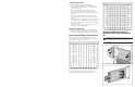
Fibre Channel Signal Connectivity
The following diagram illustrates the Fibre Channel signal
connectivity between server bays
and the interconnect modules via
the backplane for the p-Cl
ass server enclosure.
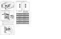
The following diagram illustrates the Fibre Channel signal
connectivity between server bays
and the interconnect modules via
the backplane for p-Class server
enclosures with enhanced
backplane components that support high-density blade servers.
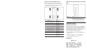
Upgrading GbE2 Interconnect
Switches with a SAN Connectivity
Kit
CAUTION: Removing a BL p-Class GbE2 Interconnect Switch from
a powered enclosure will result in the loss of network
communications between the server blade and the network
infrastructure.
1. Remove the GbE2 Interconnect Switch.
2. Remove the GbE2 Interconnect Switch cover.
http://h18000.www
1.hp
.com/produ
cts
/storagework
s
/san/doc
ument
ation.
ht
ml