
BladeSystem p-Class SAN Connectivity Kit Quick Setup Instructions
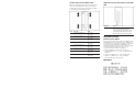

3. Install the Fibre Channel Signal Conditioning Card.
4. Replace the GbE2 Interconnect Switch cover.
5. Install the OctalFC Interconnect Module.
6. Reinstall the GbE2 Interconnect Switch.
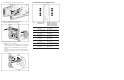
7. Install the trans
ceivers and cable.
a. Install transceivers in Fibr
e Channel ports corresponding to
the ProLiant blade servers with Fibre Channel connectivity
.
b. Install the transceiver SFP module into the port until it
clicks (1).
c. Insert the optical cable into
the transceiver SFP module (2).
d. When fully seated, both the transceiver and the cable click
into place.
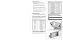
OctalFC Interconnect Module Ports
Item Backplane for p-Class
Server Enclosures
Backplane for p-Class Server
Enclosures with Enhanced
Backplane Components that
Support High-density Blades
1 Fibre Channel port for
server bay 1
Fibre Channel port for server
bay 1 and/or 9
2 Fibre Channel port for
server bay 2
Fibre Channel port for server
bay 2 and/or 10
3 Fibre Channel port for
server bay 3
Fibre Channel port for server
bay 3 and/or 11
4 Fibre Channel port for
server bay 4
Fibre Channel port for server
bay 4 and/or 12
5 Fibre Channel port for
server bay 5
Fibre Channel port for server
bay 5 and/or 13
6 Fibre Channel port for
server bay 6
Fibre Channel port for server
bay 6 and/or 14
7 Fibre Channel port for
server bay 7
Fibre Channel port for server
bay 7 and/or 15
8 Fibre Channel port for
server bay 8
Fibre Channel port for server
bay 8 and/or 16